A B B C Circuit Diagram

Edf6 A B B C Circuit Diagram Wiring Resources

Case 480 Wiring Diagram Wiring Diagram

Quantum Equivalent Circuit Of Zcg Download Scientific Diagram
Holdsworth bsc eng msc fiee rc.

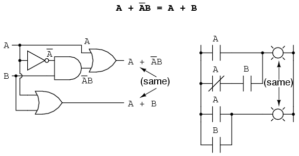
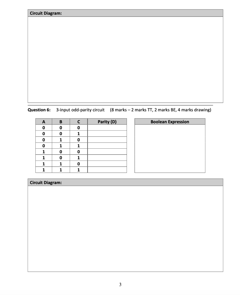
A b b c circuit diagram. A digital logic circuit or system is usually made up of combinational elements such as nand and nor gates and memory elements which may for example be discrete flip flops or latches. Suppose the logic circuit having 3 inputs a b c will have its output high only when a majority of the inputs are high. You could do that with boolean algebra or just by drawing a karnaugh diagram. Logic circuit suppose the logic circuit having 3 inputs a b c will have itslogic circuit.
Industrial automation 525 views. Browse and share custom components for use in circuit diagram. The circuit diagram of a c b would look something like. Draw the circuit diagram of the following expression f a b c d using nand gates.
Source v120 by circuit diagram. For instructions on how to use this in circuit diagram desktop see installing components. In this playlist all the types of circuits are solved seperately in each videos like hydraulic circuits pneumatic circuits electro. Fernando ballen cardenas 7391 views.
Cascade method for pneumatic circuit abb a duration. However you can simplify a b b c to a c b. Note that complimented inputs are available. The final expression ba c is much simpler than the original yet performs the same function.
Hi i came across an exam question today which asked me to draw a circuit diagram using only 1 not gate 1 xor gate and 1 or gate of the following expression f abc abc abc abc which ive simplified to fab bc ac ive been trying for hours but i cant seem to find an. Welcome to the lecture series of mechatronics circuits. Available in the web editor. If you would like to verify this you may generate a truth table for both expressions and determine qs status the circuits output for all eight logic state combinations of a b and c for both circuits.
A B B C Circuit Diagram Wiring Diagrams Resources
Solved Cmpt 101 Lab 8 Worksheet Maximum 50 Marks Instr
Circuit Mechanisms For The Maintenance And Manipulation Of

Gn 0580 Circuit Diagrams The Following Circuit Diagram Represents

Hs 7647 Logic Diagram To Boolean Expression Free Diagram

Hs 7647 Logic Diagram To Boolean Expression Free Diagram

Amazon Com Dzg Universal Hid Wiring Harness Kit Wire Connectors
Edf6 A B B C Circuit Diagram Wiring Resources
