Ab C D Circuit Diagram
Circuit Diagram Boolean Expression Ab C D Solved Draw A Circuit

Q 4 9 An Abcd To Seven Segment Decoder Is A Combinational
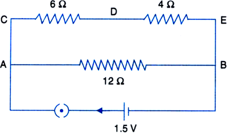
In The Circuit Diagram Shown In Fig Calculate I The Current
Class c amplifiers typically use a single active device that is biased well into its off region.
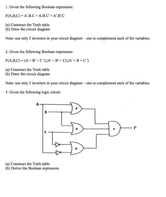
Ab c d circuit diagram. Chapter 4 exercises and answers. Step 1 set up the truth table ab c x step 2 write the and term for each case where the output 0000 00 10 each case where the output. Draw the logic diagram corresponding to the following boolean expressions without sim plifying them. As the signal is applied the top peaks of the signal cause the device to run into conduction but obviously for only a small portion of each input waveform cycle.
Suppose the logic circuit having 3 inputs a b c will have its output high only when a majority of the inputs are high. Logic circuit diagram 3. Draw a logic circuit diagram using nand or nor only to implement the boolean function fab ab ab asked jul 20 2019 in computer by helisha 687k points basics of boolean algebra. Obviously this circuit is much simpler than the original having only two logic gates instead of five.
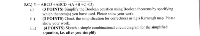
You could do that with boolean algebra or just by drawing a karnaugh diagram. However you can simplify a b b c to a c b. Truth tables a truth table is a chart of 1s and 0s arranged to. Answers are in blue except for circuit diagrams.
A bc ab acd b a bc da b d c ab. Logic circuit suppose the logic circuit having 3 inputs a b c will have itslogic circuit. For exercises 1 17 mark the answers true and false as follows. Download the notes topic 1.
In this case we would begin with the sub expression a c which is an or gate. The circuit diagram of a c b would look something like. The next step in evaluating the expression ba c is to multiply and gate the signal b by the output of the previous gate a c. Here are some logic gate circuit problems.
Draw a logic circuit for a bc. At the output the circuit uses a high q l c resonant circuit. Draw a logic circuit for a bc d. Draw a logic circuit for ab ac.
Draw a logic.
Solved Digital Logic Computer Science Please Solve Show Work

A Schematic Diagram Of A Thz Abcd Spectroscopic System In Both
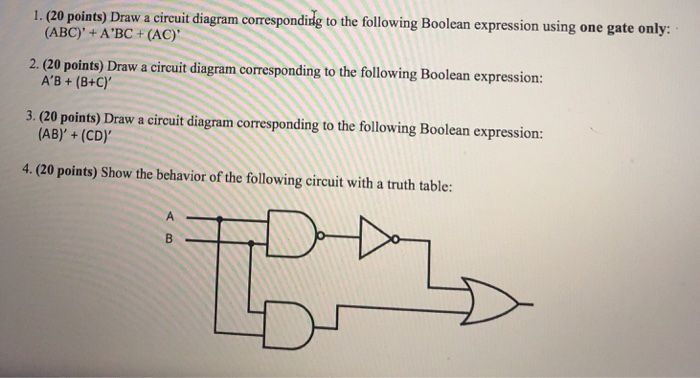
Solved 1 20 Points Draw A Circuit Diagram Correspondid

Test Paper Digital Logic Design And Application Mumbai
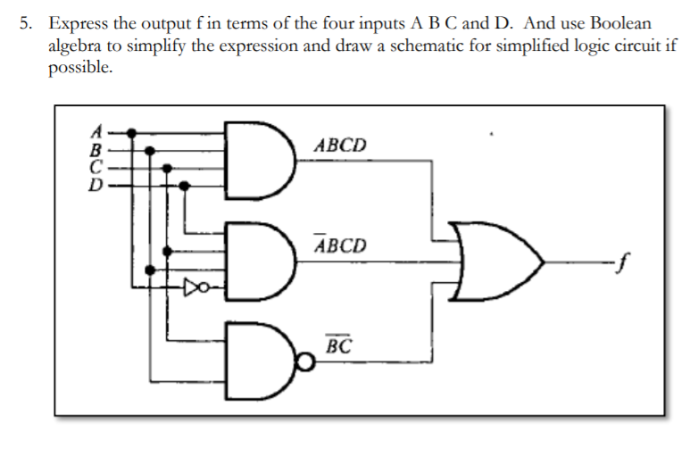
Solved 5 T F In Terms Of The Four Inputs A B C Express T

Hs 7647 Logic Diagram To Boolean Expression Free Diagram
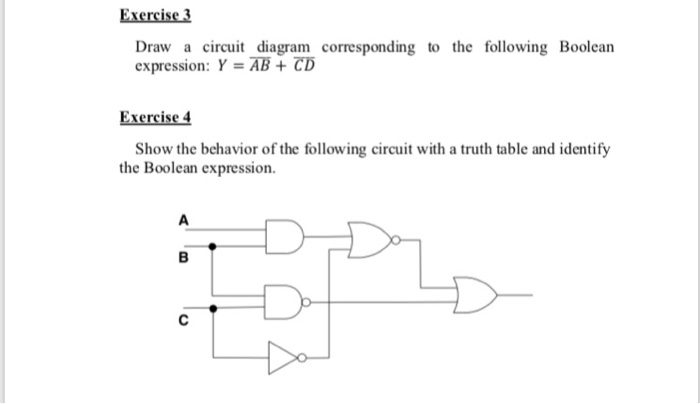
Solved Exercise 3 Draw A Circuit Diagram Corresponding To

Fe 6849 And Gate
Computer Science
