Assemble Circuit Diagram Of Ups

Zb 2727 Simple Ups

Mini Ups System For Router Mobile Charger Diy Project

18152217 12v 600va Inverter Project Using A Transformer Salvaged
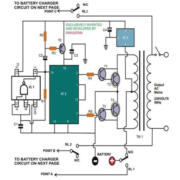
This is the circuit diagram of a simple ups that can deliver 12v unregulated and 5v regulated dc.
Assemble circuit diagram of ups. A wide variety of assemble circuit diagram options are available to you such as number of layers output type. Uninterruptible power supply also used in many countries where energy shortage is a main issue. The transformer t1 steps down the mains voltage to 12v ac and then the bridge b1 rectifies it. About 5 of these are other pcb pcba 5 are pcba and 23 are multilayer pcb.
The bridge b1 can be a 2a bridge. If its an ups the inclusion of a battery charger circuit becomes imperative. Circuit diagram with parts list. The capacitor c1 must be rated at least 25v.
The capacitor c1 must be rated at least 25v. The battery charger circuit. Keeping the low cost and simplicity of the design in mind a very simple yet reasonably accurate battery charger design has been incorporated in this uninterruptible power supply circuit. The bridge b1 can be a 2a bridge.
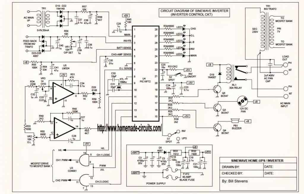
Uninterruptible power supply have very core importance for control of sensitive devices such as computers induction machines medical equipments and many other things. If such a bridge is not available make one using four 1n4007 diodes. Sukam sinewave inverter transformer data 650va 850va and wiring diagram. Ups 4 duration.
Circuit diagram with parts list. Diy 12v 7ah 18650 ups replacement battery. The transformer t1 can be a 230v ac primary 12v secondary3a step down transformer. Wiring diagram parts list design worksheet duration.
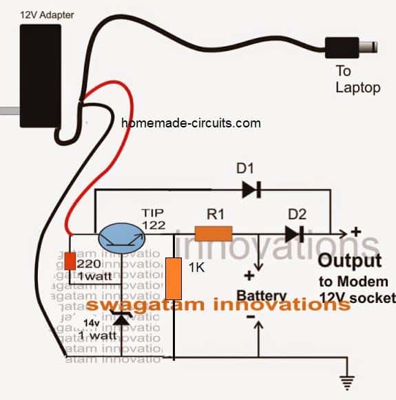
Get contact details address of companies manufacturing and supplying inverter card inverter pcb inverter pcb card across india. I have also added practical circuit for ups in this article. Normally a laptop charger is specified with 18v so for charging a 12v battery this needs to be lowered to 14v. Looking at the given dc modem ups circuit diagram we can see a simple yet interesting configuration involving a couple of diodes d1 d2 and resistor r1.
Sanchai 269380 views 1718. The transformer t1 can be a 230v ac primary 12v secondary3a step down transformer. Find here inverter card inverter pcb manufacturers suppliers exporters in india.

Solved 12v Ups Diy Circuit Attiny85 Lm317 Raspberry Pi Forums

Dc To Ac Converter 12v To 220v Voltage Converter

2000 Watt Inverter Circuit Diagram 24v 2kva Circuit Diagram With
Https Encrypted Tbn0 Gstatic Com Images Q Tbn 3aand9gctfbgod Ykzdbah5mydu Sakty9o5anrzfiw8l7bj1abfczk Yy Usqp Cau
Apc Ups Schematic Diagrams Atmega32 Avr
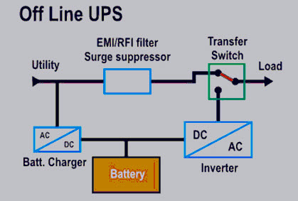
Types Of Uninterruptible Power Supply Devices With Working
3 Simple Dc Ups Circuits For Modem Router Homemade Circuit Projects
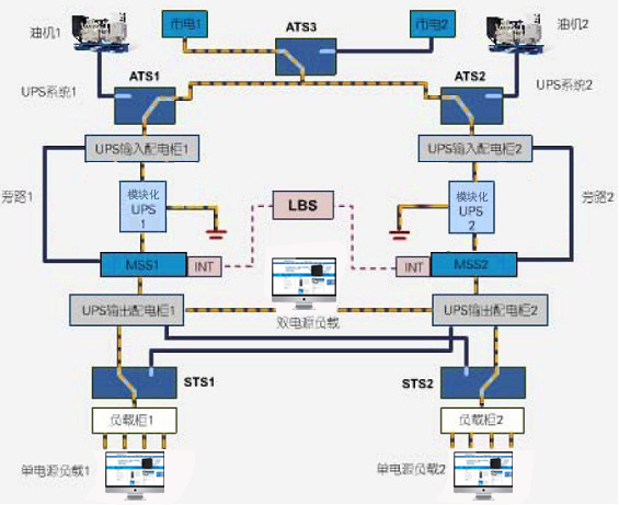
Dual Bus Modular N X
4 Simple Uninterruptible Power Supply Ups Circuits Explored
