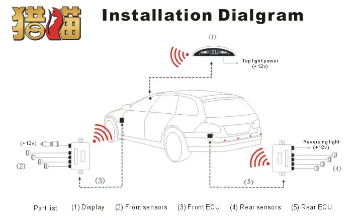
Backup Sensor Wiring Diagram
Connect the positive and negative power provide wire of backup camera installation with the positive and negative leads of backup lightweight backup light.

Backup sensor wiring diagram. Wiring diagram index name description page aa power distribution frc 3 ab power distribution frc 4 ac power supply circuit protection 34 ef 5 ad power supply circuit protection 44 ef 6 ae grounding 7. Ratchets and wrenches 638985 views. Place the sensor display or speaker. Variety of kenworth wiring diagram pdf.
A wiring diagram is a simplified traditional photographic representation of an electric circuit. Dont connect the ability provide wire of backup camera with visual signal or tail lightweight. Variety of backup camera wiring schematic. Sign up today to access the guides.
It shows the components of the circuit as streamlined shapes as well as the power and signal links in between the devices. The display module wire is 16 long. A wiring diagram is a simplified conventional photographic representation of an electrical circuit. Perfectly fit your car with universal hole saw.
Place the brain in a convenient spot in your trunk. Drill the holes for your bumper pop in the sensors and thread the wires and plug in to the brain. When the backup lightweight activates the backup camera activates furthermore. When this one particular wire gets 12 volts it tells the headunit to now switch to the yellow rca video.
The sensor wire is 8 long connecting to the controller box. It reveals the components of the circuit as simplified forms and the power and signal links in between the tools. Learn how to access vehicle repair guides and diagrams through autozone rewards.