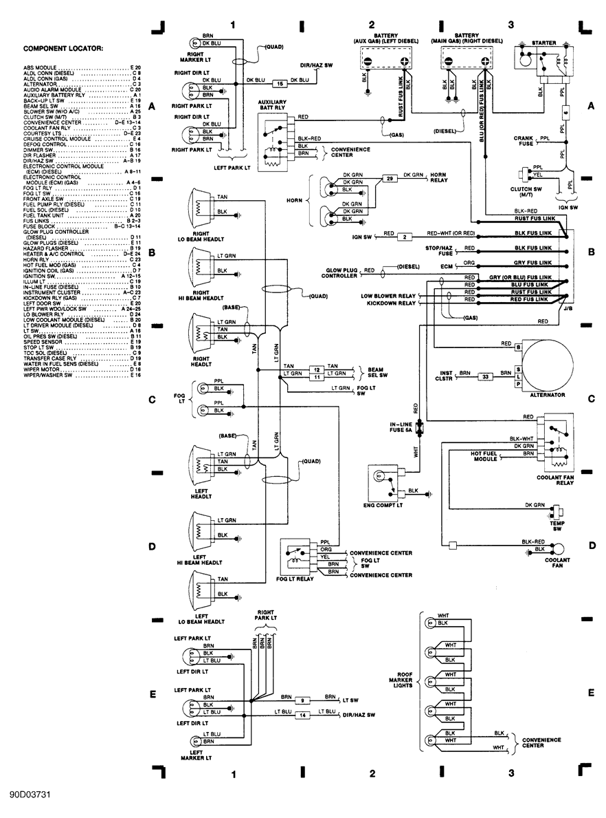
Base Engineering Wiring Diagram
Engineering data engineering data meter socket circuit diagrams 178 data subject to change without notice.

Base engineering wiring diagram. 10 pole test switch internal potential wiring of 13 14 15 jaw sockets front view. Equipment functional view wiring diagram ladder logic industrial ethernet configuration summary properties connect a3. To exploit the savings potential wire setting automats can be fed all necessary data using the available interfaces. 3 other components.
Due to the common engineering base database the circuit diagram and the layout diagram can even be created in random order. Includes all of bases patented remote truck functions and emergency stop complying with dot 49cfr and csa b620 requirements for off truck remote emergency stop on lpg delivery trucks. Base engineering wiring diagrams 10 10 danishfashion mode from wiring diagram electrical source1010danishfashion modede 2005 freightliner m2 wiring diagram 3 12 tierarztpraxis ruffy from wiring diagram electrical source312tierarztpraxis ruffyde. Base engineerings new procontrol3 integrated fuel delivery system another exceptional remote control system that can do everything an on board computer can do plus more.
Wiring diagram the wiring diagram is used for the representation of electrical components in their approximate physical location using their specific symbols and their interconnections using lines. Check list 1 module summary in1in2 in3 in4 in5in6 24v 0v in7in8 in9 in10 io1io2 io3 io4 in11 in12 in13 in14 io5io6 io7 io8 in15 in16 in17 in18so1a so1b so2a so2b. 3o 4wire watthour reactive ct rated meter sockets 13 pt. Wiring diagram since wiring connections and terminal markings are shown this type of diagram is helpful when wiring the.
Base engineering is a world leader in developing radio remote control technology for the petroleum industrysince 1996 over 100000 base systems have been employed around the globe to increase job safety and productivity. This configuration requires a base module with fid 2 or higher. The cooperative and integrated engineering base platform provides the basis for the electrical design of highly complex plants that meet the requirements of industry 40. Vertical and horizontal lines are used to represent wires and each line represents a single wire that connects between electrical components.
This supports parallel bundling of processes and helps keeping even tight deadlines.


