Basic Garage Door Light Wiring Diagram

Outdoor Garden Led Solar Light Circuit
How To Add A Light
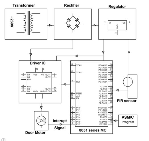
Automatic Door Opening System Using Pir Sensor
Wiring a garage planning your garage wiring.

Basic garage door light wiring diagram. Of sheathing through the wire opening in the box. In the video i touch on some basic safety precautions when doing electrical work and describe the proper way to hook up wiring to an outlet and a light switch. A wiring diagram is a simplified conventional pictorial representation of an electric circuit. There is a ton of information on basic wiring principles on the web as well as a number of great books on the subject too.
A typical symptom is that the door. Of sheathing off the wires and thread the wires and about 12 in. Help support our channel by. 800 x 600 px source.
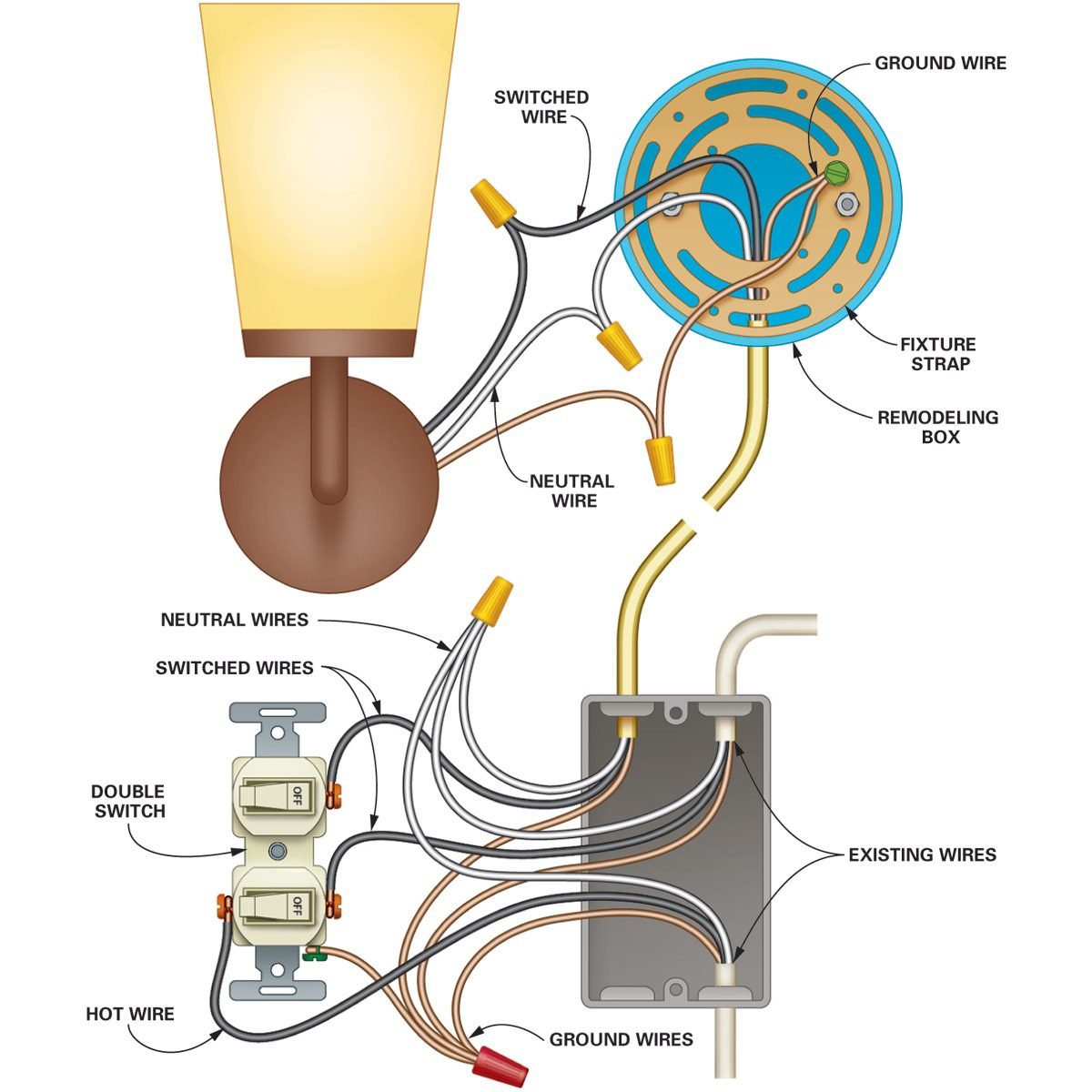
To run a cable from one box to another pull cable off the coil strip at least 8 in. Do this by connecting the new green ground wire to the existing ground wire at the first box see ground metal boxes and fixtures below. Figures a b and c below show the wiring diagrams to add outlets and a switched outlet for a hanging light. At the end of this internet site there is additionally a chamberlain garage door opener schematic image gallery if the image above is not nearly enough for you.
Its important to make sure all the boxes are grounded. Collection of liftmaster garage door opener wiring schematic. Wiring a garage is really not all that complicated if you have a basic understanding of electricity and follow widely published guidelines. Wiring a 4 way switch subpanel installation this entry was posted in indoor wiring diagrams and tagged diagram do it yourself handyman handywoman home improvement home renovations home wiring house wiring light light switch power switch wiring wiring diagram.
It shows the parts of the circuit as simplified shapes and also the power and signal connections between the devices. I have 4 double sockets on the garage walls ready to wire i have a 2 way rcd unit too and a couple of strip lights. In this video i use a wiring diagram to show how garage door beam sensors work and how to determine if your problem is a wiring component or aiming issue. It detects probable improper wiring conditions in standard 110 125 vac outlets provides 6 probable wiring conditions that are quick and easy to read for ultimate efficiency lights indicate if wiring is correct and indicator light chart is included tests standard 3 wire outlets ul listed light indicates if wiring is incorrect very handy and easy to use.

Installing A Garage Door Opener Wired To Motorcycle Hi Beam 7

Garage Door Light Wiring Diagram For Safety Wiring Diagram

A6f5b85 Tail And Stop Light Wiring Diagram Free Picture Wiring

M 140 Automatic Light Sensor Wiring Diagram And User Manual

2210e Garage Door Light Wiring Diagram For Safety Wiring Resources
Schematic Liftmaster Wiring Diagram
Installation With Liftmaster Opener Wiring Openers Garadget
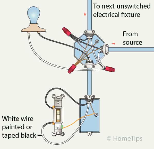
Standard Single Pole Light Switch Wiring Hometips
Electric Garage Door Opener Stopped Working No Power Green
