Block Diagram Linear System
Http Www Ee Ic Ac Uk Pcheung Teaching De2 Ee Lecture 2011 20discrete 20time 20systems 20 X1 Pdf
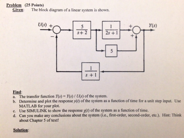
Solved Given The Block Diagram Of A Linear System Is Sho

Control System Closed Loop Open Loop Control System Electrical4u
H 1 for a linear unity feedback system fig.
Block diagram linear system. In this section system block diagrams are introduced which are based on the relationship between the suspension force and the associated winding currents as derived in the previous section. In other words practical representation of a control system is its block diagram. Gscsrs where rs laplace transform of the input variable. We know that the input output behavior of a linear system is given by its transfer function.
A unity feedback system is one in which the primary feedback b is identically equal to the controlled output c. Let us consider the block diagram of a closed loop control system as shown in the following figure to identify these elements. Hello friends in this blog article we will learn block diagram algebra in the control system. 75 system block diagrams of bearingless machines.
The above block diagram consists of two blocks having transfer functions gs. This algebra deals with the pictorial representation of. A block looks on paper exactly what it means. Control block diagram reduction signal flow graph mason gain steady state laplace root locus pid controlbode plot lead and lag compensation examples.
7 7 any feedback system with only linear time invariant elements can be put into. Learn all the block diagram reduction rules just by watching this one simple video. The block diagrams are drawn for a few basic synchronous motor structures ie an spm. When designing or analyzing a system often it is useful to model the system graphically.
Block diagrams are a useful and simple method for analyzing a system graphically. It is easier and better to derive the transfer function of the control element connected to the system separately. It will include block diagram reduction rules some block diagram reduction examples and solutions. The basic elements of a block diagram are a block the summing point and the take off point.
Two critical laws explanation please watch video along with this description to get better understanding rule. It is not always convenient to derive the entire transfer function of a complex control system in a single function. 7 6 continued 76 unity feedback systems definition 77. The block diagram is to represent a control system in diagram form.
Gc324809 Linear Amplifier For Radio Amateur Use Block Diagram Vara
Chapter4 Note

Control Systems Block Diagrams Wikibooks Open Books For An Open
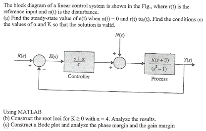
Solved The Block Diagram Of A Linear Control System Is Sh

Motion Control Systems A Complete Family Of Motion Control

How To Draw Signal Flow Graph From A Block Diagram Linear
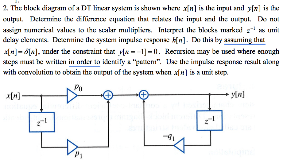
Solved The Block Diagram Of A Dt Linear System Is Shown W

B Lecture3 The Transfer Function And Block Diagram Automatic

20 Sim Webhelp Library Signal Block Diagram Differentiate Fo
