Boiler Limit Switch Wiring Diagram
How To Install Wire The Fan Limit Controls On Furnaces

Fan Limit Control Installation Faqs

Boiler Limit Switch Wiring Diagram Wiring Library
The first wiring diagram figure 7 is of a boiler with a float type lwco.
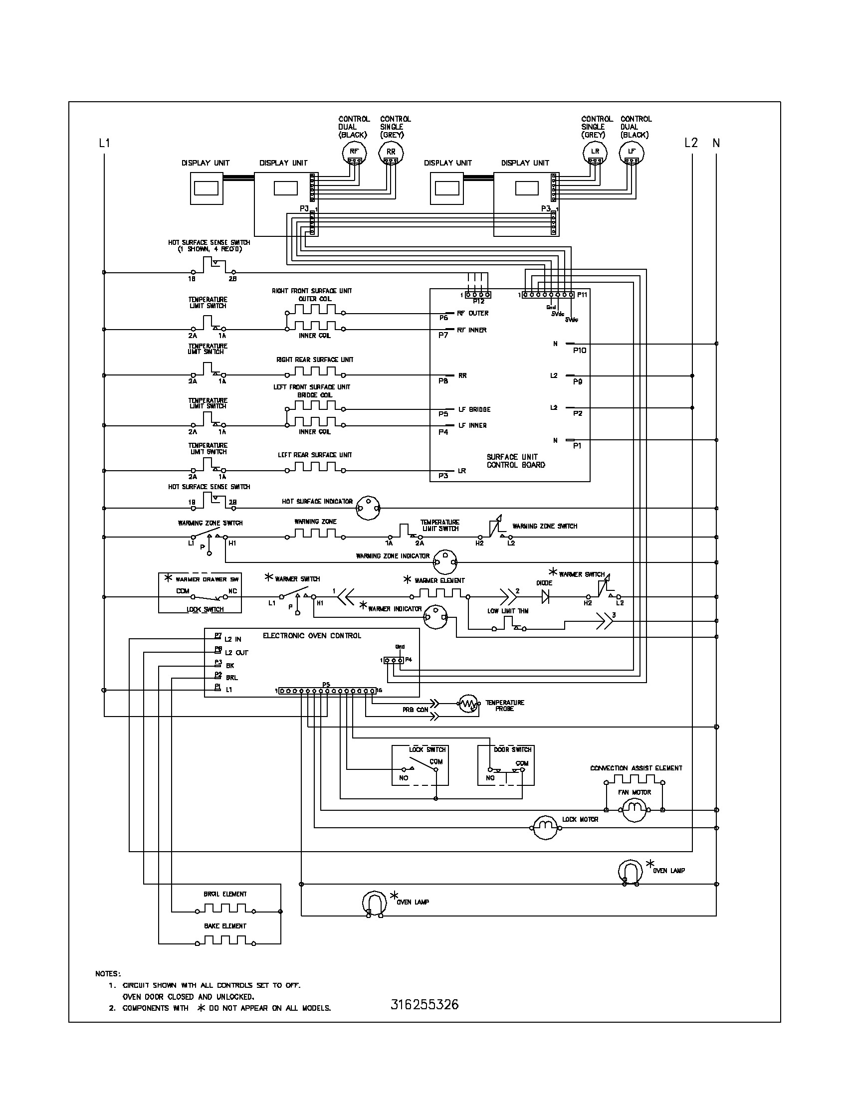
Boiler limit switch wiring diagram. 24 volt thermostat forced air no zone valve wiring. Zone valve 24 volt thermostat transformer wiring. Wiring the boiler the load is now a boiler. Gas boiler wiring application guide us.
When the boiler has enough water the circuit between terminals 1 and 2 is closed and the circuit between terminals 3 and 4 is open. Here above left is a photo of a more traditional single function heating boiler limit controls. The power input terminal is called the common terminal and is used to connect the switch to a power source. Es2 esc series 3 series 2 boiler control.
Featuring burnham brand iq boiler control and intelligent hydronic control systems. Aquastat heat exchanger wiring. The boiler switch gets installed into the room thermostat cables on the boiler wiring diagram if you have an existing. Fan limit switch or snap disc on furnace black brown fan speed tap wires connect prefered speed tap wire fan relay with fan and limit switch rc y w b r o rh g w 24 volt thermostat end switch motor circuit led wy c terminal 2 to g terminal 1 to c.
See figure 4 page 20 this wiring diagram shows 120 v coming from l1 of a circuit breaker through a switch powering a boiler control and returning through l2 back to the neutral bar of the circuit breaker box. Fan relay fan limit switch wiring. Part 1 in a series on wiring uk central heating systems. Wiring diagram for two 24 v thermostats and a relay.
Zone valve 24 volt thermostat transformer zoning pump wiring. A limit switch is used to control electrical devices by breaking and completing electrical circuits. Boiler service ideal vogue combi boiler step by step guide leeds plumber duration. In this example the aquastat or limit switch is being used on a tankless coil that happens to be on steam boiler.
Intelligent hydronic control c2013 us. Wiring application guide. Honey well triple action aquastat wiring explained low limit reverse action with additional zone relays how to properly wire to prevent loosing domestic hot water. It has three terminals.
Illustration fan relay with fan and limit switch central boiler author. It is abbreviated com the other terminals are the normally open no. Guide to single function heating boiler limit controls use of a single function limit switch on boilers tankless coils. 24 volt thermostat zone valve wiring.

Document

Wiring Residential Gas Heating Units

Wiring Basics For Residential Gas Boilers

Hot Air Furnace Manufacturer S Diagrams Hvac Troubleshooting
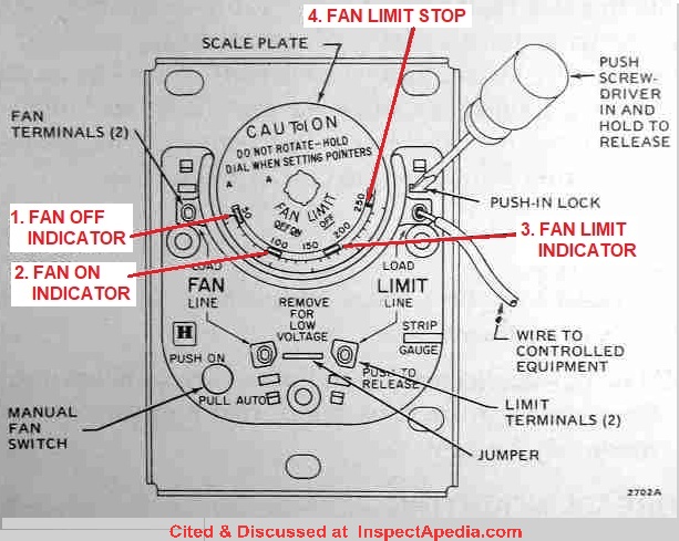
How To Install Wire The Fan Limit Controls On Furnaces
004 Boiler Limit Switch Wiring Diagram Wiring Library

New Combi Boiler Thermostat Wiring Diagram Thermostat Wiring Ac

Mo 3863 Wiring Limit Switches To Furthermore Limit Switches

How Do I Connect A C Wire To An Utica Peg112cde Steam Boiler
