Camshaft Wire Diagram
Jeep No Start Ricks Free Auto Repair Advice Ricks Free Auto

Avcs Cam Sensors Nasioc

I M Trying To Install A Cam Sensor On An 02 Maxima Any Idea Where
Connect the 5v to the blueblack wire through a resistor id probably start with a 10k ohm resistor.
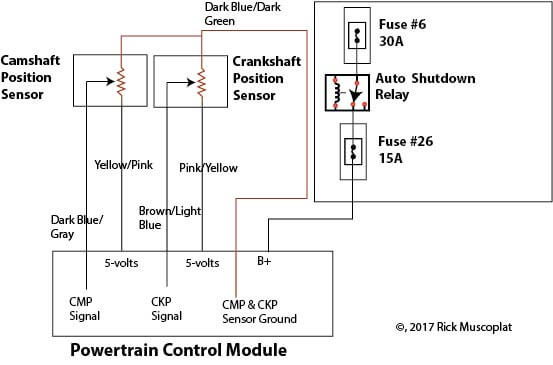
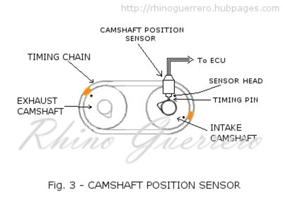
Camshaft wire diagram. It is mounted at the end of the intake camshaft see fig. The camshaft position sensor used in kia rio 2010 is the hall effect type. Need to know the wiring schematics for a camshaft my colors are blue and black and need to wire the plug answered by a verified hyundai mechanic. I need the wiring diagram for the camshaft position sensorand the crankshaft position sensor dodge 2002 neon question.
Each wire shown in the diagrams contains a code which identifies the main circuit part of the main circuit gage of wire and color fig. The cam and crk sensors are types of speed. Connect the ground of your oscilloscope to the black wire and the tip to the blueblack wire. Wiring diagram courtesy of alldata current phaser description.
Alternate cam x107 connector 40 pin connector pin cylinder wire color 7 7 orange black 34 6 yellow black x108 connector 40 pin connector pin cylinder wire color 6 8 dark blue white 7 5 tan white. To identify which circuit code applies to a system refer to the circuit identification. It rises back to 12 volts when the pin leaves the sensor head. Camshaft position sensor cmp operation.
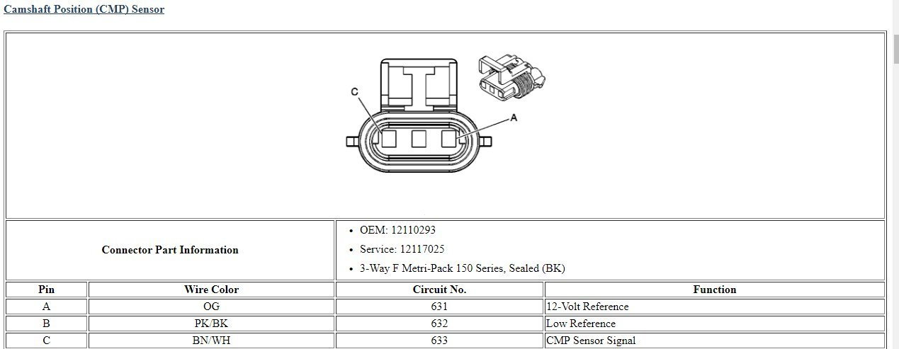
Need to know the wiring schematics for a camshaft my colors are brownblue and black and need to wire the plug. Workshop and repair manuals service owners manual. On 2 wire sensor engines the distributor stator or camshaft position cmp sensor is a single hall effect magnetic switch. I need a wiring diagram for the 5 prong plug on a 2004 hyundai santa fe fuel.
The cmp sensor provides the camshaft position information called the cmp signal which is used by the powertrain control module pcm for fuel synchronization. Wiring diagrams spare parts catalogue fault codes free download. Pin cylinder wire color 6 3 pink black 7 2 light green black 34 5 tan white 35 8 dark blue white connectors after. Now move a metal object like a screwdriver or wrench around the sensor in the place where the camshaft would usually be.
When the camshaft timing pin comes close to the sensor head the voltage at the signal wire drops to zero.
2005 Cam Sensor Connector Wiring Corvetteforum Chevrolet

12 Nissan Murano Engine Wiring Diagram Engine Diagram In 2020

Ad65c4 Ford Taurus Camshaft Position Sensor Wiring Diagram
Camshaft Wire Diagram Wiring Diagram

Al 7068 Wiring Diagram P72 Ecu Download Diagram
Dtc P0340 Camshaft Position Sensor Circuit Malfunction Diagnosis
1589300275000000
Atoz Camshaft Wiring And Voltage P0343 Hyundai Forums
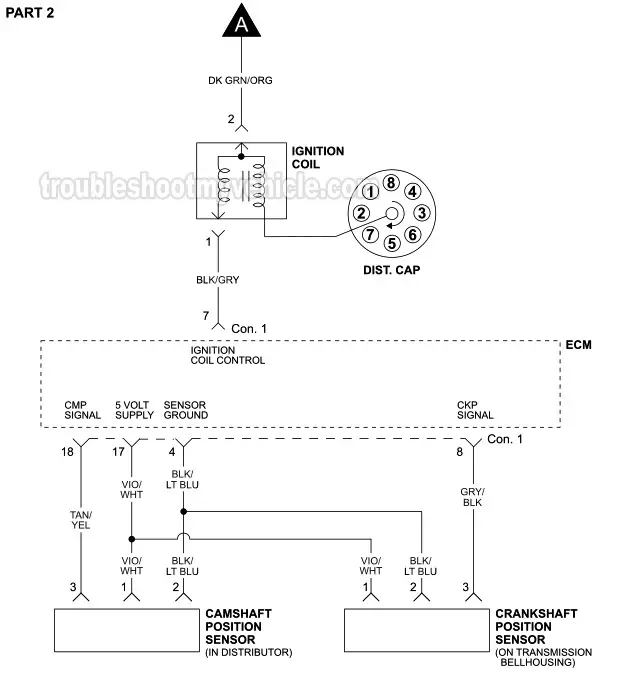
Ignition System Wiring Diagram 1996 1997 3 9l V6 Dodge Ram 1500
