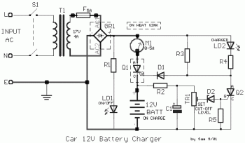
Car Battery Charger Schematic Circuit Diagram

Simple Car Battery Charger And Indicator Circuit Diagram

Simple Schematic Diagram Simple Circuit Car Battery Charger
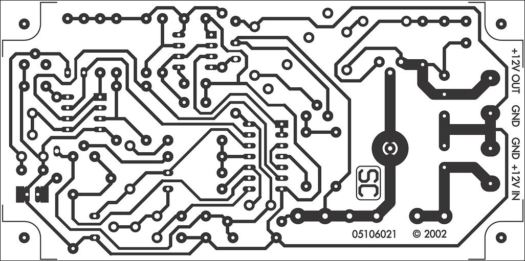
12v Car Battery Charger Under Repository Circuits 22148 Next Gr
This is a schematic diagram of a full automatic 12v battery charger for charging the batteries of automobiles etc.
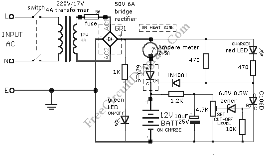
Car battery charger schematic circuit diagram. This design additionally includes a twin indication system in the form of a battery charging indicator and a low battery buzzer indicator. This ac voltage is rectified and filtered to obtain an unregulated dc voltage used to charge the battery through a relay. The battery is charged from a 230v 50hz ac mains supply. You are able to ideally take advantage of this circuit for applications such as inverters portable chargers etc.
This 12v battery charger circuit with auto cut provides the automatic cut off facility when the battery get fully charged. Before the use of this circuit you need to adjust the cut off voltage range for autocut. Share on tumblr simple 12 volt battery charger circuit diagram designed by using few easily available components and this circuit is suitable for different types of batteries needs 12 volt. R1 1kohms d1 1n4001 t1 220v17v 4a transformer r2 12kohms d2 68v 05w zener ld1 green.
The main supply voltage 230v 50hz is connected to the primary winding of the center tapped transformer to step down the voltage to 15 0 15v. Unlike many units this battery charger continuously charges at maximum current tapering off only near full battery voltage. You can use this circuit to charge 12v sla battery or 12v gel cell battery and so on. Here is a simple and easy to build circuit diagram of a 12v car battery charger.
This 12v automatic car battery charger circuit can be also use for charging other automobiles batteries. Battery charger battery circuit diagrams battery discharger battery tester circuit diagram softwares electronic keys locks ir devices low voltage circuit no comments 4 bc639 transistors are used in fan speed control circuit and speed can be adjusted with 47k trimpot on the circuit. This adjustment is done by the 10k preset and a multimeter connected with the output terminals that goes to battery. Circuit diagram of automatic battery charger this automatic battery charger circuit is mainly involves two sections power supply section and load comparison section.
A car battery charger schematic description. This is a simple car battery charger with indication. Voltage monitoring circuit for 12 volt lipo battery pack schematic circuit diagram tda7293 100w rms amplifier schematic circuit diagram ps1502d 0 15v adjustable 15v 72v stage power supply schematic circuit diagtram. May 20 2020 in.
Car battery charger circuit working principle.
12v Car Battery Charger Electronic Schematic Diagram

12v Gelled Electrolyte Battery Charger
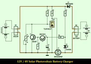
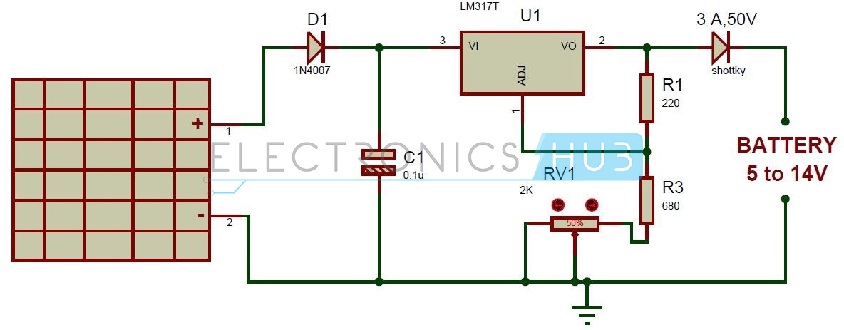
12v 4a Solar Photovoltaic Battery Charger Electronic Schematic
12v Battery Charger Circuit With Overcharge Protection

Automatic Car Battery Charger Schematic Circuit Diagram
12 Volt Battery Guardian Circuit Circuit Diagram And Instructions

Simple Battery Charger Circuit Wiring Schematic Diagram 3
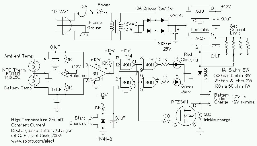
Temperature Controlled Nicd Charger
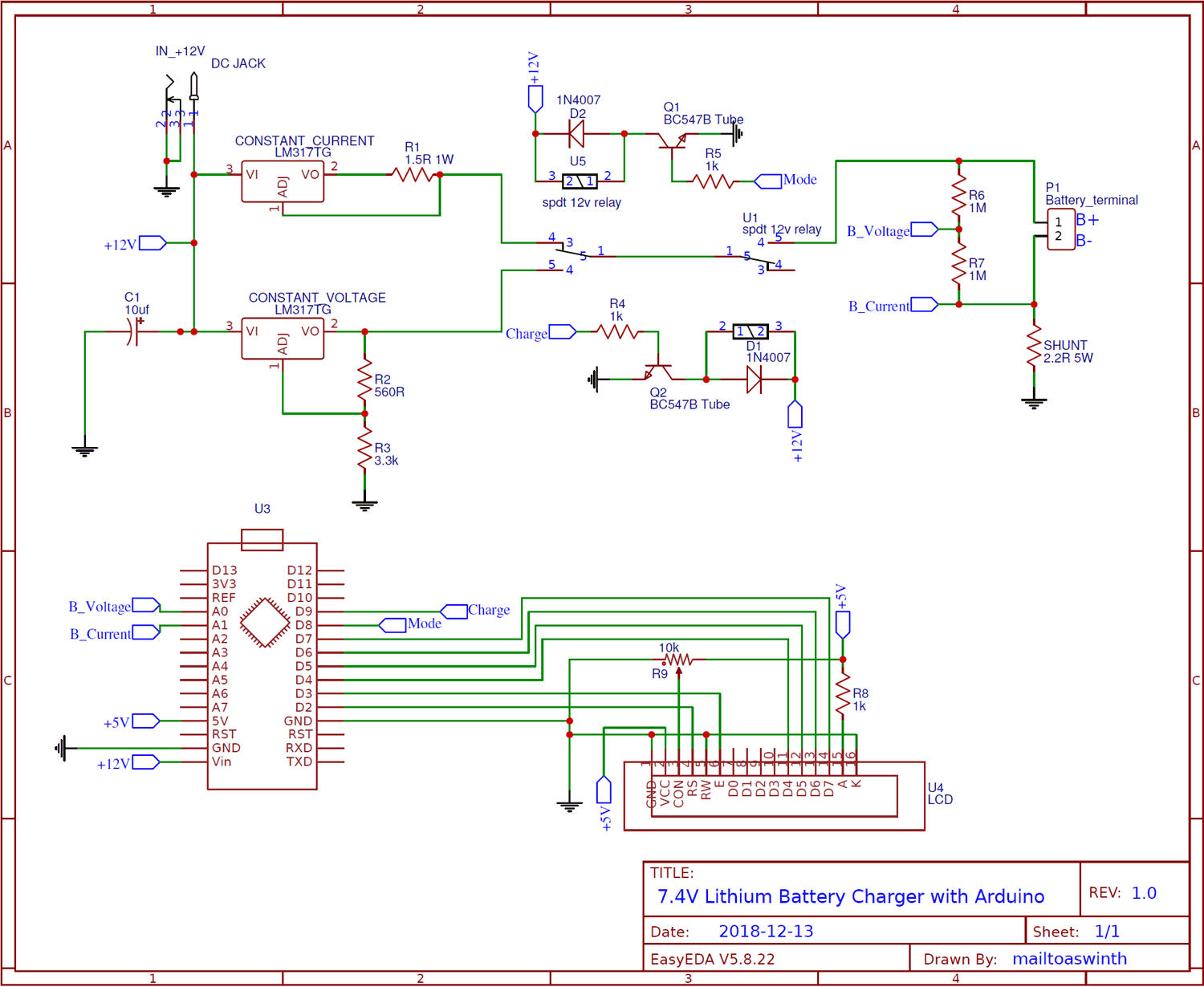
7 4v Two Step Lithium Battery Charger Circuit Cc And Cv Mode
