Circuit Board Wiring Diagram For Rc

The Almost Complete Guide To Electric Rc Cars 10 Steps
Free Circuit Simulator Circuit Design And Simulation Software List

Wiring Diagram Electric Rc Helicopter Com
The first section discusses the components which may need to be installed the second section addresses the question of what type of wire to use the third section discusses the different types of connector and.

Circuit board wiring diagram for rc. Drone wiring diagram detail. Circuit diagrams can be divided into two categories pictorial circuit diagram and schematic circuit diagram. For the discussed rc helicopter remote control circuit a 6 channel rf remote module would be required exactly similar to the one which was used for our earlier simplest drone remote control circuit. You can find plenty of letters on terminal connections including rc and rh but have no idea of what they mean or what the difference is.
Air conditioning thermostats are no exception. Free pcb files and circuit diagram. By connecting realistic electrical components with the wiring a pictorial diagram makes it easy and quick for viewers to. What is distribution board.
We can split the base drone wiring diagram into multiple parts as below. Images of circuits of rc control car and remote. Osd and transmitter and camera and. Making a circuit board from scratch duration.
Distribution board is also known as fuse board panel board. It shows how the electrical wires are interconnected and can also show where fixtures and components may be connected to the system. The range of the remote control should be as per the required specifications of the rc helicopter range here its supposed to be within 1km. This increase of speeds can be enforced by configuring the remote control relays as per the following wiring diagram.
Wiring model boats this article is intended to explain the basics of wiring a radio controlled model boats. Flight controller connection wiring diagram. A wiring diagram is a simple visual representation of the physical connections and physical layout of an electrical system or circuit. Pictorial circuit diagram pictorial diagrams are much easier to understand than schematic circuit diagrams.
You look at a circuit board or instruction manual and you see plenty of letters or numbers but often no corresponding explanation of what they mean. As you see above the base of drone wiring diagram there are so many components are need to connected with each others. Distribution board is a safe system designed for house or building that included protective devices isolator switches circuit breaker and fuses to connect safely the cables and wires to the sub circuits and final sub circuits including their associated live phase neutral and earth conductors.
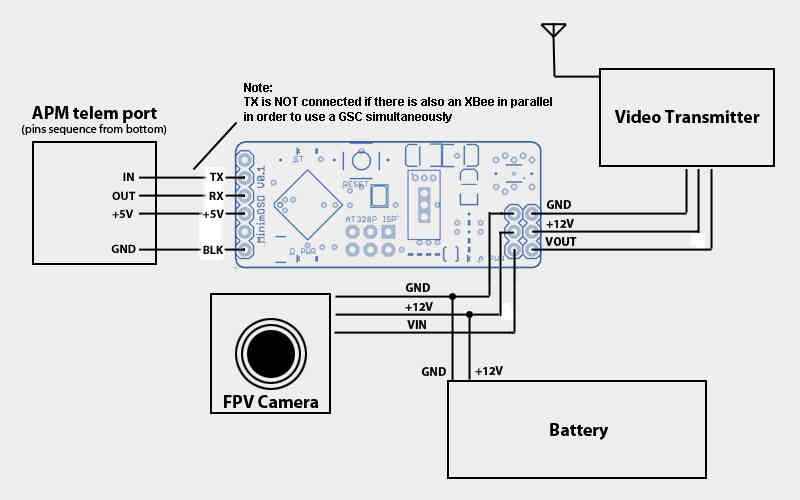
Minim Osd Quick Installation Guide Copter Documentation
1
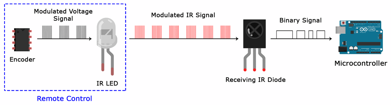
How To Set Up An Ir Remote And Receiver On An Arduino Circuit Basics
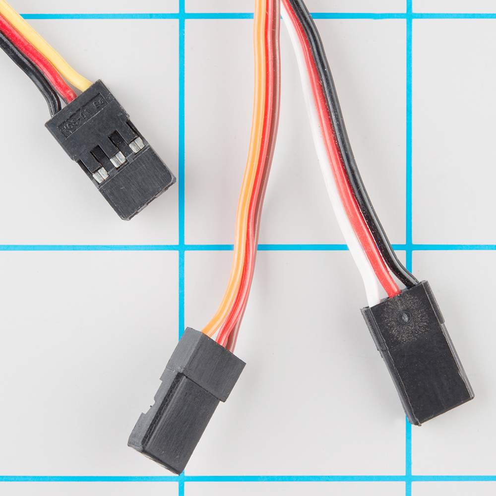
Hobby Servo Tutorial Learn Sparkfun Com
Https Encrypted Tbn0 Gstatic Com Images Q Tbn 3aand9gcqikrw55z3lcmos 5c7fgx Vy2pyez Wv4gioi3rgassicnw8iq71wxt9r4qivvhgu Usqp Cau

Hr 0829 Rc Circuit Board Free Diagram
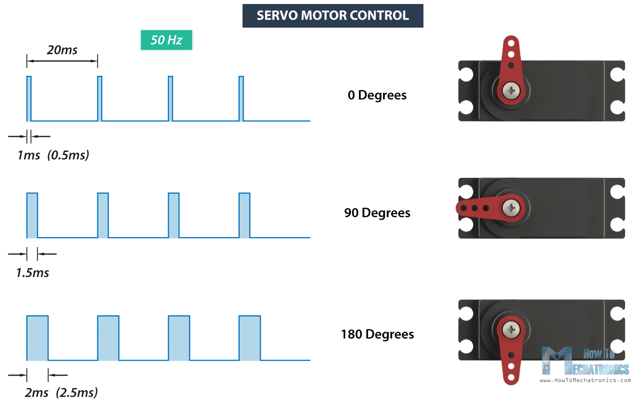
How Servo Motor Works How To Control Servos Using Arduino
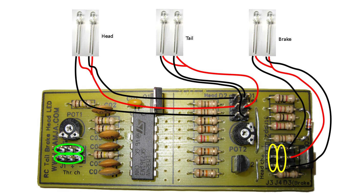
Rc Car Head Tail And Brake Lights Led Control Board Lamja Com

Sg 1203 Rc Car Electric Circuit Board For Sg 1203 1 12 Drift Rc
