Circuit Diagram Of Yagi Antenna
The Yagi Uda Antenna An Illustrated Primer Duo Security
Antenna Audio Circuit Diagram Electric Video Yagi Antenna Icon

Fm Transmitter Electronic And Computer Project
In understanding the basic yagi antenna theory the different elements of the yagi antenna react in a complex and interrelated way.
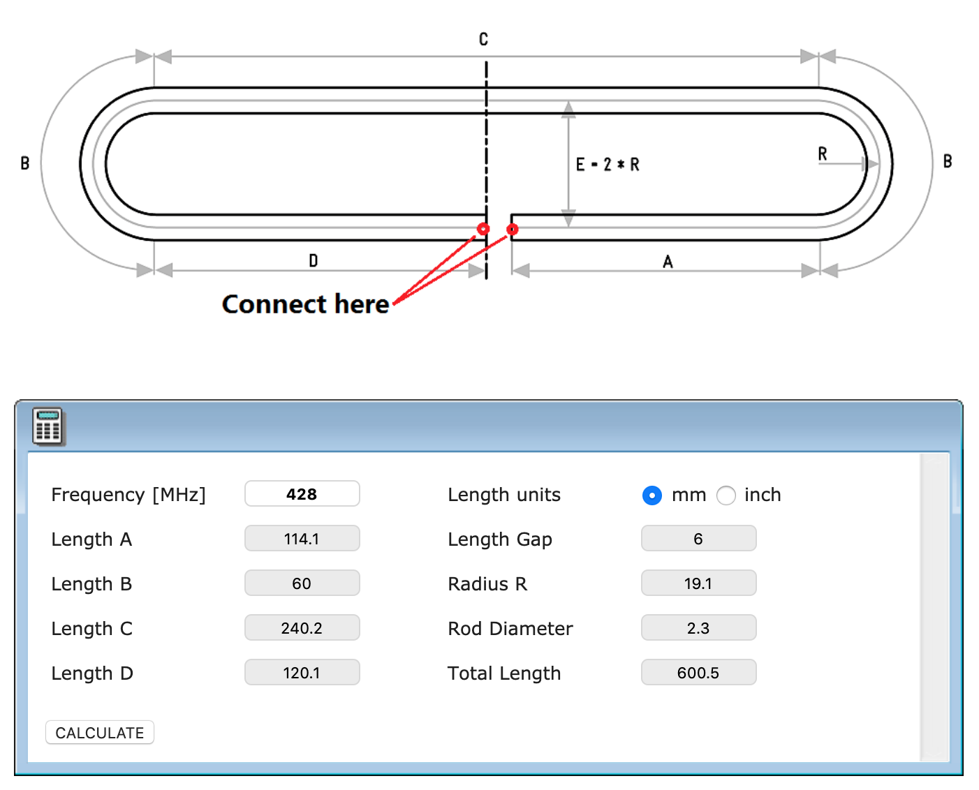
Circuit diagram of yagi antenna. Gt 166 n where n is the number of elements in the yagi antenna. Connect the usb device to the antenna. Wideband active antenna circuit p. A well designed yagi antenna as per the design given below can cover a line of site distance of even 5 kms with just 1 watt rf power.
With the yagi uda array and parabola antenna the radio waves are radiating in a specific direction so they are said to be directional antennas beam antennas. Yagi antenna this is diagram about yagi antenna you can learn. Circuit diagram of yagi antenna posted on april 2 2019 by admin yagi uda anteena designing steps rh elprocus com antenna circuit diagram with obstructions digital tv wiring diagram online rh 2 code3e co homemade hd antenna diagrams clear buick power antenna wiring diagram rh 27 sbaphotography nl cruise control horn relay. Yagiuda antennas consist of a single driven element connected to the transmitter or receiver with a transmission line and additional parasitic elements which are not connected to the transmitter or receiver.
The antenna gain is a function of the number of dipole elements. Antenna amplifiers circuits and projects 12 browse through a total of 12 antenna amplifiers electronic circuits and diagrams. Directional antennas and non directional antennas in the diagram above with the whip antenna the radio waves are radiating in every direction equally so it is a non directional antenna. The dipole in the array is driven and another element 5 longer operates as a reflector.
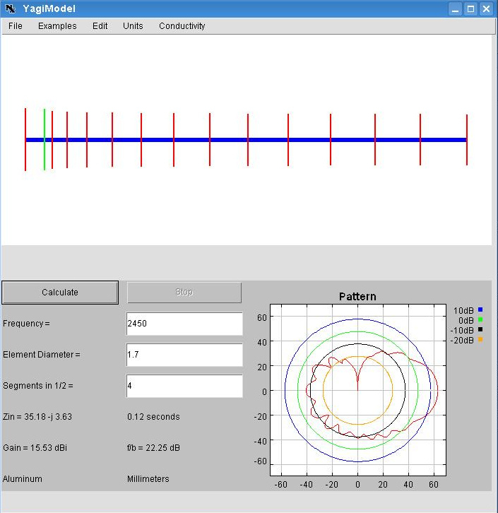
Yagi antenna design formula. I used a yagi modeler java applet to generate the diagram. Tv antenna amplifier circuit p. Trim paper clips to size and glue them to the template.
One of the major keys to understanding yagi theory is a knowledge of the phases of the currents flowing in the different elements of the antenna. A yagiuda antenna commonly known as a yagi antenna is a directional antenna consisting of multiple parallel elements in a line usually half wave dipoles made of metal rods. By circuit diagram. Use popsicle sticks to build the antennas backbone and hold it together.
The yagi antenna is a narrow band antenna designed to work only on fm channel. It has the best gain for its sizes and a correspondingly narrow main lobe beam. The most common form is the yagi uda parasitic array commonly referred to as a yagi. To improve signal transmission or reception in specific directions basic elements either vertical or horizontal can be combined to form arrays.
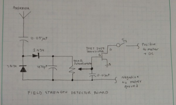
A 30 to 50 cm whip antenna provides reception from 10 mhz to over 220 mhz.
How Can I Make This Circuit Design More Sensitive Chegg Com
Https Nptel Ac In Content Storage2 Courses 108101092 Week 11 Yagi Uda And Log Periodic Antennas Pdf

Commissioning Tip 1 Antenna Orientation

Story Writting Fm Transmitter
What Is A Gamma Match In The Context Of The Driven Element Of A
High Gain Yagi Wifi Antenna

Construction Details Of 2m Yagi With Images Ham Radio Ham

Long Range Fm Transmitter Circuit Diagram 2km Fm Transmitter Circuit
Stacked Yagi Antennas Vladimir Umanets Ua9ba
