Circuit Diagram Single Phase Motor Starter Panel

How Does Work Single Phase Submersible Motor Starter In Hindi

Https Encrypted Tbn0 Gstatic Com Images Q Tbn 3aand9gctb2amp2ohuxjyah9stancncwrgzpx4vu Cow Usqp Cau
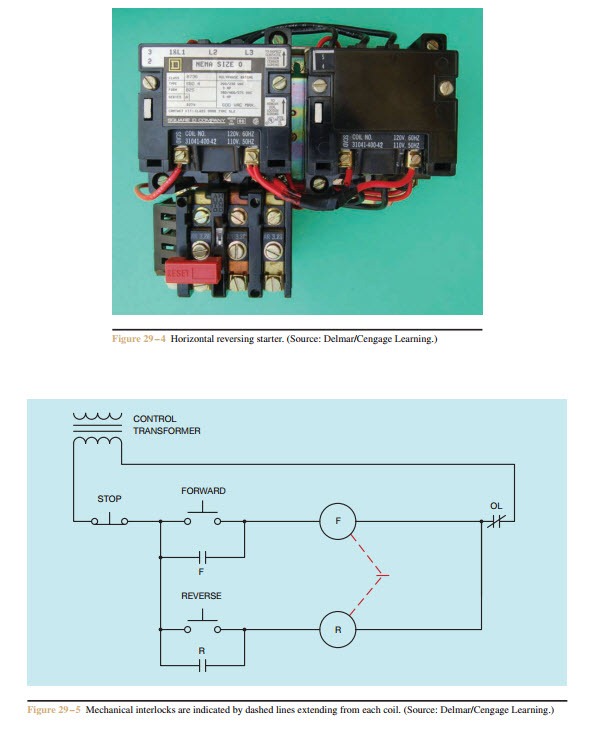
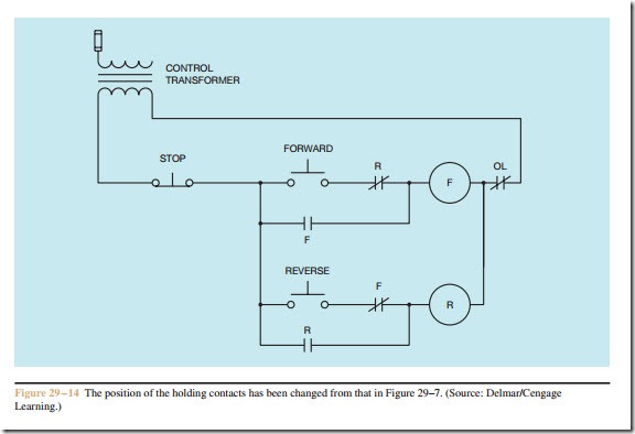
Forward Re Verse Control Developing A Wiring Diagram And
This three phase power from the alternators is further transmitted to the distribution end through transmission lines.

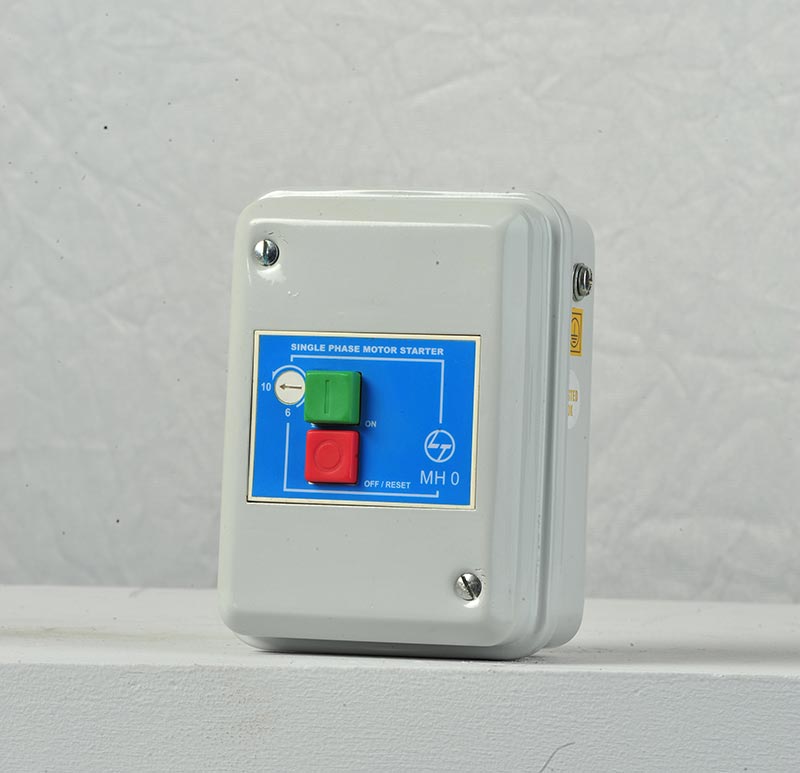
Circuit diagram single phase motor starter panel. Mar 14 2017 single phase motor contactor wiring diagram elec eng world. The simplest form of motor starter for the induction motor is the direct on line starter. It comprises an enclosure in steel or plastic a contactor start contact link wires and stop start buttons. Single phase motors controls 1 15 hp 282 300 8110 date codes 11c19 newer 1 15 hp 282 300 8610 relay l1 l2 yel blk red line power from two pole fused switch or circuit breaker and other control if used.
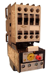
The thermal overload is supplied as a separate item. Direct on line dol motor starter description the direct on line motor starter dol is designed to switch a single or three phase induction motor at rated voltage. The direct on line motor starter dol consist a mccb or circuit breaker contactor and an overload relay for protection. The diagram below shows the wiring for a single phase motor and the path through the contactor and overload.
Motor contactor magnetic relay and contactor. Electromagnetic contactor which can be opened by the thermal overload relay under fault conditions. The above diagram is a complete method of single phase motor wiring with circuit breaker and contactor. Contactor with overload wiring diagram single phase.
Please see the attached diagram for guidance. Dol starter control diagram three phase. In the above one phase motor wiring i first connect a 2 pole circuit breaker and after that i connect the supply to motor starter and then i do cont actor coil wiring with normally close push button switch and normally open push button switch and in last i do connection between capacitor. This diagram illustrates possible wiring using a tesys d lc1d contactor and tesys lrd overload lrd and stop control is assumed to be by operation of the stop button on the overload.
Here are a few notes about wiring up my small lathe motor. Single phase motor. Contactor design and rating contactor nameplate. 5 6 circuit documents general.
Reverse forward motor starter control and power circuit with diagram motor windingstar delta starterdol starterstar delta connection3 phase dol starter connection diagram direct online starter. Star delta starter wiring diagram 3 phase with timer. To motor yel blk red blk blk yel 1 2 5 red yel run capacitor start capacitor blk org blk red ground lead ground lead line power. A complete guide about single phase submersible motor starter wiring diagram explanation or single phase 3 wire submersible pump box wiring diagram in english video tutorial.
Singlephase Electrical Automation L T India
Wiring A Single Phase Motor Through A 3 Phase Contactor How And Why

Float Switch Installation Wiring Control Diagrams Apg

Contactor Wiring Diagram For Single Phase Motor
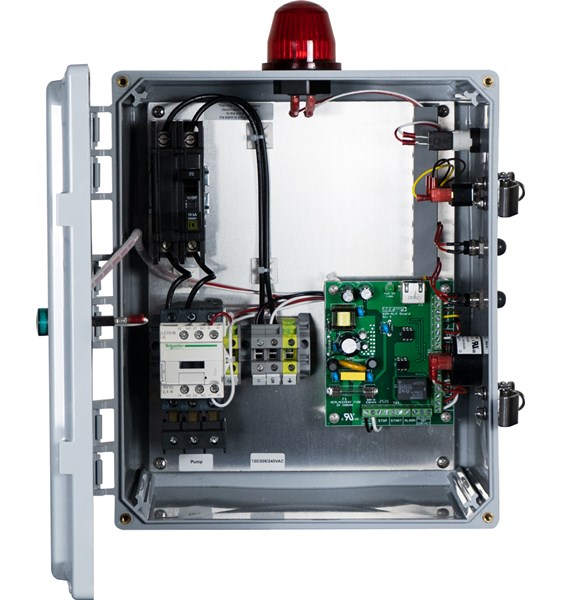
Sim A Single Phase Simplex Sump Pump Control Panel See Water Inc
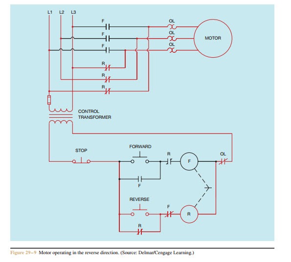
Forward Re Verse Control Developing A Wiring Diagram And
Forward Re Verse Control Developing A Wiring Diagram And

Control Panel For 2 H P Submersible Pumps 2 Phase Model Lmps

120 Volt Capacitor Start Motor Wiring Diagram Diagram Base Website
