Circuit Diagram Tester
Short Circuit Tester Circuit Diagram Measuring And Test Circuit

Battery Tester Circuit Schematic Eeweb Community

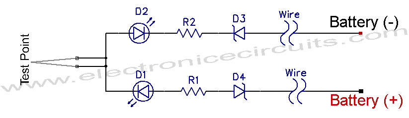
Leakage And Continuity Tester Detailed Circuit Diagram Available
The circuit will detect if there is water in the soil of any plant and light up the led.
Circuit diagram tester. We have previously built a transistor tester circuit to test transistor and now we are building simple op amp tester circuit to test the lm741 ic. Pin diagram of lm741 is given below. The tester was made out of some junk parts i had on hand as well as a couple of op amps and a 555 timer. Ic lm741 is advanced and commonly used op amp as voltage amplifier.
Multi wire and cable electronic tester circuit project. The test is based on a timed cycle of charge where two voltage compartors indicate 37 and 63 of charge. See more ideas about circuit diagram circuit electronics circuit. Simple servo tester schematic circuit diagram.
Referring to the schematic the capacitor is connected to the terminals labeled c. Cable testers are electronic devices used for testing electrical and electronic connections and strength in signal cables or different wired assemblies. How to make this capacitance tester. Now how to test the components for fault.
Circuitlab provides online in browser tools for schematic capture and circuit simulation. They are generally used for checking of path connectivity and it also checks the improper wiringyou can use a cable tester device to check the communication strength of cable from the. This circuit will work on soil but you can also use it to test or detect moisture in other substances. We can observe the remote control state by listening to.
The resistor r2 is a potentiometer to adjust the level on which you want to make the led on. Some circuits would be illegal to operate in most countries and others are dangerous to construct and should not be attempted by the inexperienced. These tools allow students hobbyists and professional engineers to design and analyze analog and digital systems before ever building a prototype. March 03 2019 in.
Servos are one of the basic components used in all branches of model building. May 23 2020 explore reynalddotollos board circuit diagram on pinterest. Circuit diagram of remote control tester editor electronic circuit published friday july 27 2012 here is an infrared remote control tester circuit that can be made without spenting much moneythis ir tester build around an infrared reciever module tsop1738.
Led Tv Backlight Tester
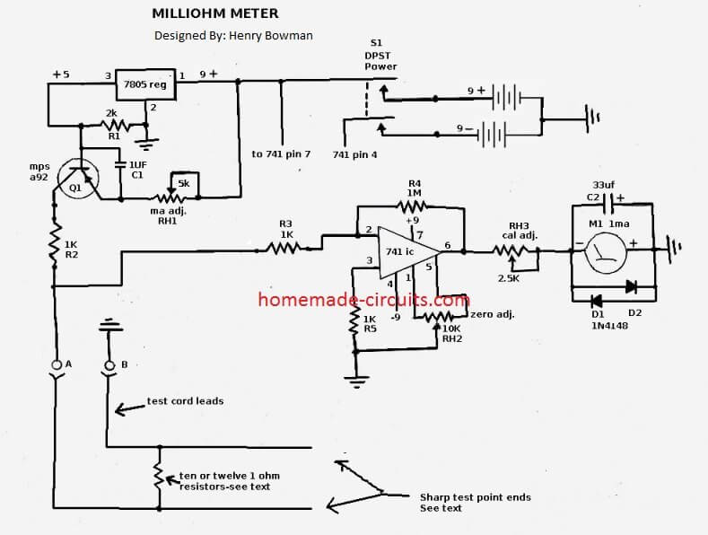
How To Make A Simple Milliohm Tester Circuit Homemade Circuit
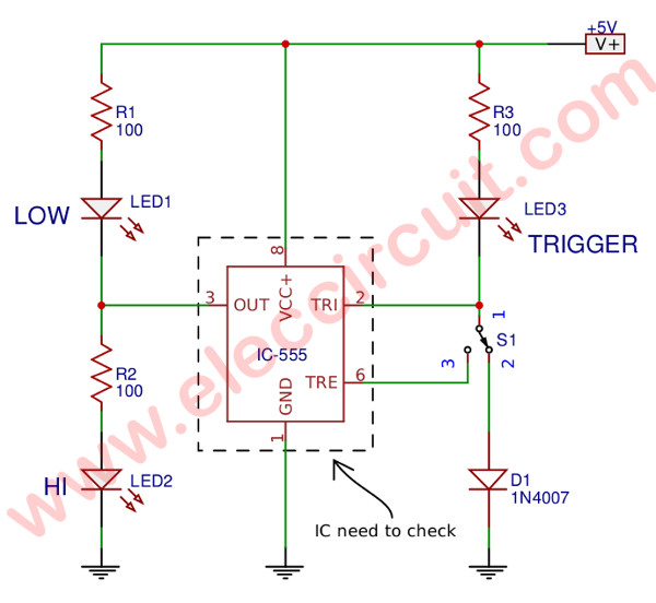
Simple 555 Ic Tester Circuit Diagram Eleccircuit Com
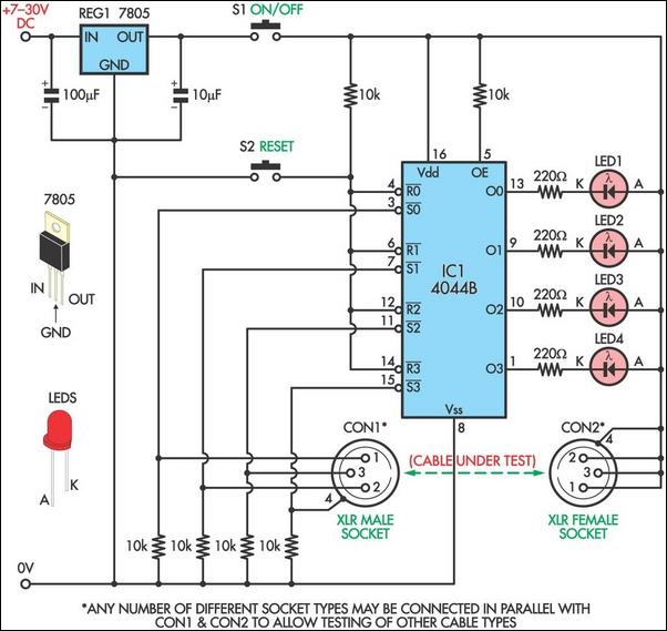
Cable Tester Uses Quad Latch Circuit Diagram

File Receptacle Tester Wiring Diagram Jpg Wikimedia Commons

Simple Continuity Tester Circuit Diagram
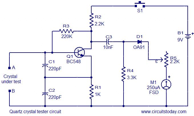
Quartz Crystal Tester Circuit
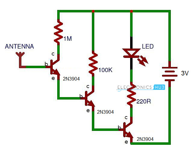
Diy Non Contact Voltage Tester Tested
Online Circuit Simulator Schematic Editor Circuitlab
