Circuit Diagram Using Ldr

Light Alarm Circuit With Ldr
Circuit Electrinic Dark Sensitive Power Switch Circuit Diagram

A Circuit Diagram Of Led Ldr And The Sensors Positions On The
Hook up the circuit shown in the above diagram using an arduino uno or adapt it to any dev board with an analog input.

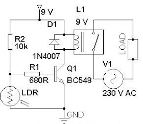
Circuit diagram using ldr. In the previous circuit we have seen a simple light detector using ldr and an op amp. This makes the voltage at the base of the transistor too low to turn the transistor on. This circuit changes the ac supply into a dc. The ldr circuit diagram works like this.
Light dependent resistor circuit. When its dark the ldr has high resistance. The fixed resistor used here is two kilohms but higher or lower resistors may work better in your situation. As you can see in the ldr circuit diagram it can be a distinguished as two smaller circuits.
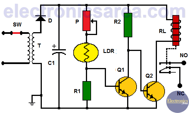
Here i am presenting simple circuit using an only resistor ldr and transistor but many types of circuits can be constructed using ldr for dark detected switching. Here is simple dark sensor circuit which can be used as automatic switch on and switch off any load using relay. The voltage divider output is feed to the analog pin of the arduino. We have tried this one in this tutorial but you can also try the second one mentioned below.
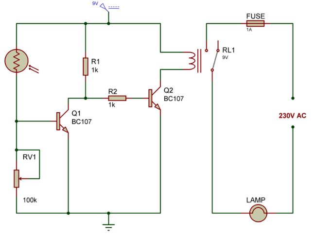
The next diagram shows how the drawback could be tackled through a sensitive precision light activated circuit that would work without getting affected from voltage or temperature variations. Light detector sensor circuit diagram. The circuit of light detector is very simple and easy to build with very few components. A voltage divider made using ldr ldr1 and a potentiometer rv1 b output led d1 in our switching circuit made using a transistor bc547 q1.
Working of ldr controlled led using arduino. The required dc voltage of the ldr circuit is supplied from a bridge rectifier circuit or a battery. The circuit of ldr is an electronic circuit built with ldr relay darlington pair diode resistors shown in the below circuit diagrama voltage supply is given to the load. It uses just two transistor to perform the light detection operation.
First heres a quick demonstration of how to use an ldr. As per the circuit diagram we have made a voltage divider circuit using ldr and 100k resistor. It automatically turns on and off street lights. Automatic street light control systemsensor using ldr transistor bc 547 very simple.
In this circuit the ldr r5 pot r6 and resistors r1 and r2 are configured with each other in the form of a wheatstone bridge network. If you dont have an op amp then the above circuit will be helpful. How the ldr circuit diagram works.

Arduino Light Sensor Circuit Diagram Using Ldr And Relay With

Basic Rc Circuit Buildcircuit Com

Zz 4015 Light Sensor Alarm Circuits Download Diagram

Light Activated Switch Using Ldr Eeweb Community
Automatic Night Lamp Circuit Gadgetronicx
Light Operated Relay Circuit Using Ldr Electronics Area

Zd 9808 Aircraft Warning Light Circuit Download Diagram

Light Sensor Including Photocell And Ldr Sensor

Automatic Street Light Controller Using Ldr
