Common Schematic Symbols Used In Circuit Diagrams
Electronic Circuit Symbols Component Schematic Symbols

Electrical Wiring Symbols Meanings And Drawings
Electrical And Electronics Symbols Analyse A Meter
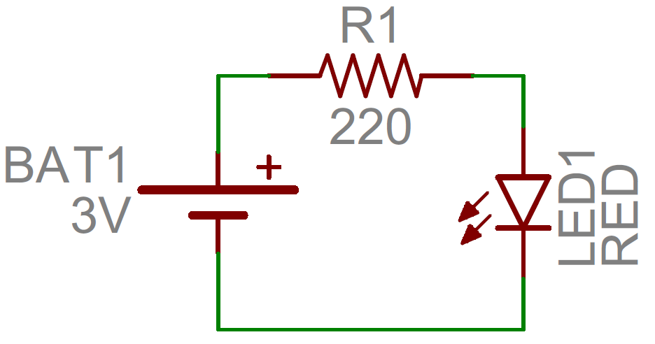
A large and a small line is suppose to represent one battery cell so that the image below would suggest a two cell battery of 3 v.

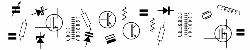
Common schematic symbols used in circuit diagrams. They are mostly used to draw a circuit diagram and are standardized internationally by the ieee standard ieee std 315 and the british standard bs 3939. Electrical symbols or electronic circuits are virtually represented by circuit diagrams. Common schematic symbols used in circuit diagrams limit multi switch point symbolsmm label label d dd ka kb k mechanical linkage optional nc no pj y td. To be able to read schematics you must know the schematic symbols.
Discusses common circuit symbols found in circuit diagrams. In electronic circuits there are many electronic symbols that are used to represent or identify a basic electronic or electrical device. A circuit diagram electrical diagram elementary diagram electronic schematic is a graphical representation of an electrical circuita pictorial circuit diagram uses simple images of components while a schematic diagram shows the components and interconnections of the circuit using standardized symbolic representations. Here is an overview of the most used symbols in circuit diagrams.
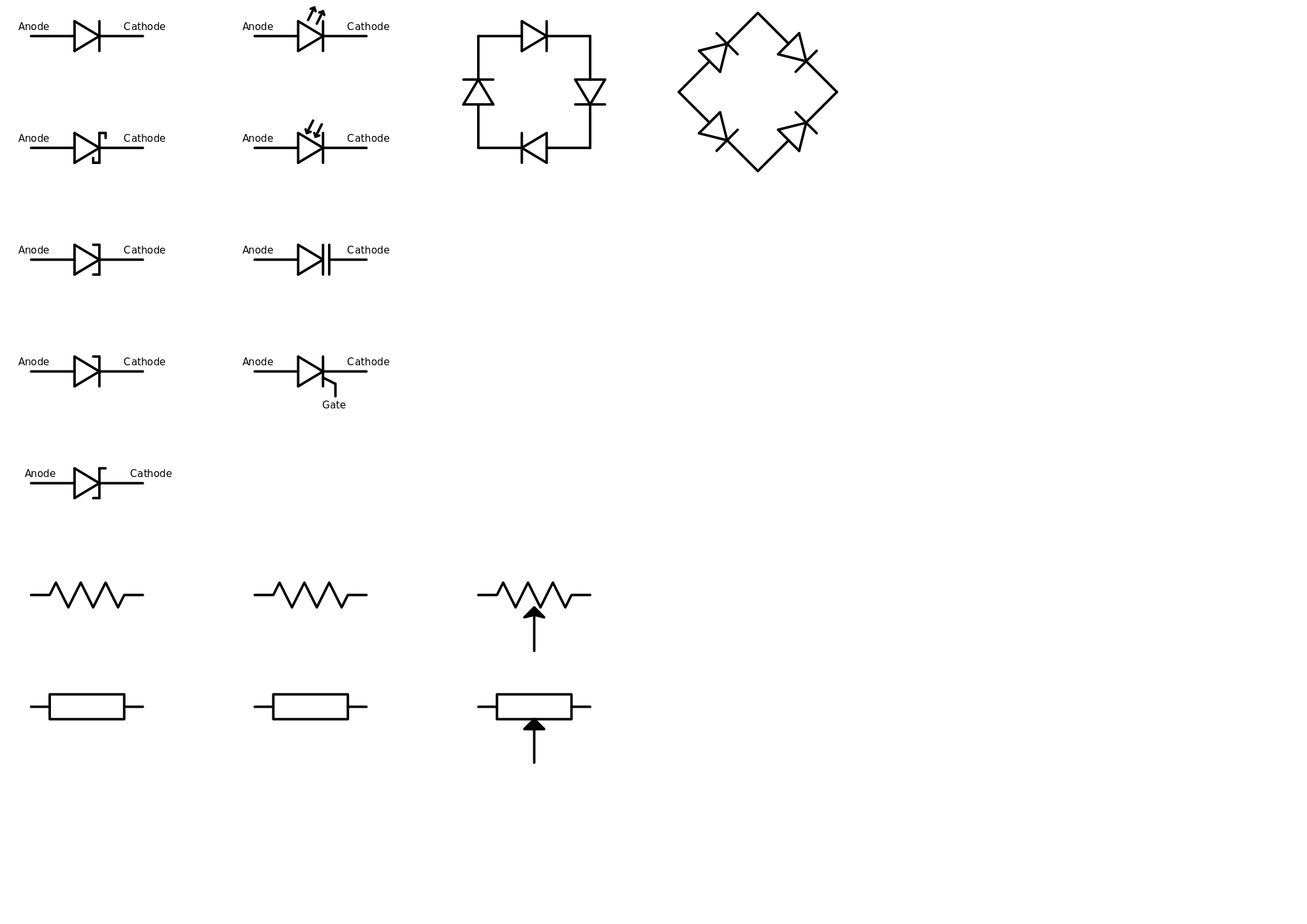
Bw landscape created date. An electronic symbol is a pictogram used to represent various electrical and electronic devices or functions such as wires batteries resistors and transistors in a schematic diagram of an electrical or electronic circuitthese symbols are largely standardized internationally today but may vary from country to country or engineering discipline based on traditional conventions. Stresses the symbols students must know for the final exam. Circuit symbols are used in circuit schematic diagrams which show how a circuit is connected together electrically.
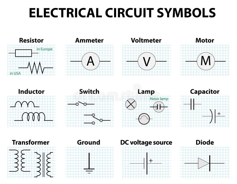
There are some standard symbols to represent the components in a circuits. 10 common electrical symbols found on electrical schematic diagrams these symbols might look like nonsense to the layman but they provide a ton of information to the ee an electrical schematic diagram might look like a nonsensical drawing to the layman but to the electrical engineer its a high level documentation that provides a ton of insight and instruction. The symbol for a battery is shown below. This article gives some of the frequently used symbols for drawing the circuits.
Electrical symbols and electronic circuit symbols are used for drawing schematic diagram. The symbols represent electrical and electronic components. The standard circuit component symbols and circuit symbols are important for circuit schematic diagrams. The standard circuit symbols are important for circuit schematic diagrams.

How To Read A Schematic Learn Sparkfun Com
Wiring Diagram Symbols Commonly Hvac Wiring Diagrams Wiring
How To Read Schematics

A1dbb Common Electrical Symbols Wiring Diagram Wiring Library

How To Read And Understand An Electrical Schematic
Understanding Schematics Technical Articles
How To Read A Schematic Learn Sparkfun Com

Schematic Symbols The Essential Symbols You Should Know

How To Read Circuit Diagrams 4 Steps Instructables
