Dc Cdi Ignition Wiring Diagram

15 Cdi Wiring Diagram Motorcycle Motorcycle Diagram In 2020

100 Cdi Ignition Wiring Diagram Baja 125cc Wiring Wiring
Rz350 Super Motard Page 80 Rz Rd 350 Misc 2 Stroke Tech Bbs
Capacitor discharge ignition system working principle a cdi system.

Dc cdi ignition wiring diagram. 5 pin ac cdi wiring diagram. 13 thoughts on pinout diagram of the dc cdi david wassell i have a yg6 150cc go cart with no spark i replaced coilstatorcdi starter relaynew battery have power up to key ignition but when you turn key to start nothing happens have lights starters good my cdi box has 6 pins but my connector has 5 wires which hole should the 2 plug wire go there is only one wire but 2 pins. This type of ignition builds up a charge quickly. Each diagram includes the part and associated parts all in one wiring diagram.
For 4 cylinder engine 2 cdi units. Dc cdi with heatsink is also based on our rl78f12 series of 16 bit microcontrollers with advanced and state of the art peripherals that are very suitable for high end two wheeler ignition control modules and body control related applications including quick engine start up and precision control of spark timings. A capacitor discharge ignition works by passing an electrical current over a capacitor. Cdi circuit using an scr a few resistors and diodes.
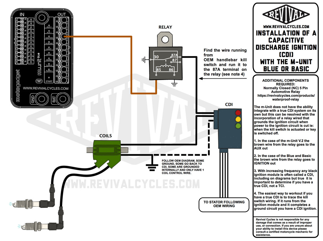
Weve categorized all our cdi wiring diagrams into ac and dc systems. Dc or ac cdi adjustable racing 6 pin cdi for dc scooters like. Showing the connection of the motorcycle component like cdi rectifier regulator ignition coil ignition switch spark plug and stator. For 6 cyl 3 cdi units can be used.
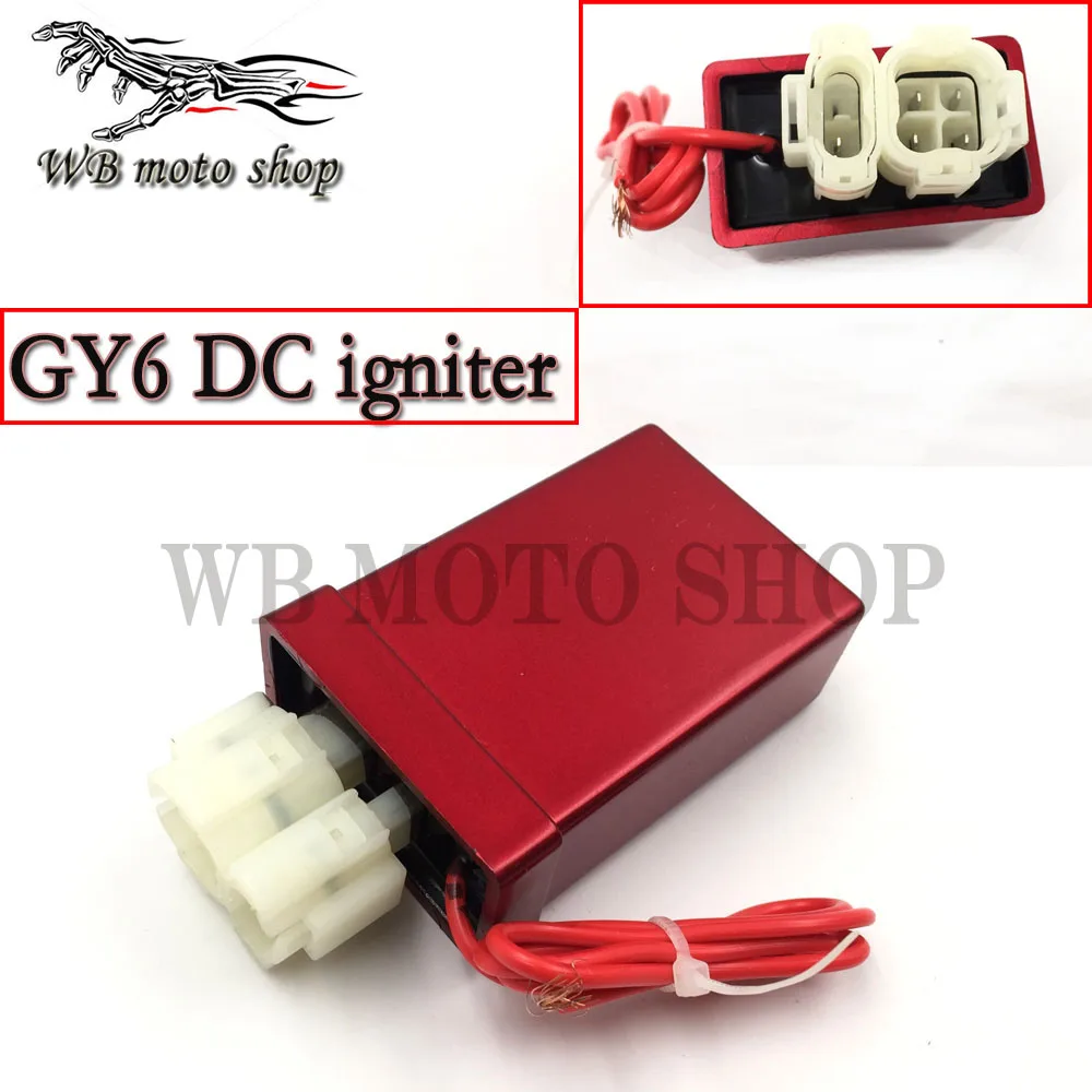
Gy6 dc fired cdi wiring diagram here is the chinese engine code chart with the example of the jog 2stroke gy6 engines are on the fron bottom left had side near the centerstand pivot. A cdi ignition starts by generating a charge and storing it up before sending it out to the spark plug in order to ignite the engine. Like all good motorcycle engineers lamberts bikes have produced part specific electrical wiring schematics. The entire circuit shown above can be used.
Cdi capacitor discharge ignition circuit demo. For more information on the difference between ac and dc supplied systems check out our cdi unit technical guide how do cdi units work currently under development. Ac cdi wiring diagram links. The cdi unit enclosed in pink box can be used to drive one dual post ignition coil.
When using multi cdi units the diode d5 encircled in blue has to be introduced to isolate the c6 of each section. That is the complete wiring diagram of. Provided below is an online pdf document for lamberts bikes 4 pin dc cdi wiring diagram. Motorcycle cdi unit wiring diagrambi cdi.

Az 2561 Wiring Diagram Further 4 Pin Cdi Box On 150cc Gy6 Cdi

Ignition Cdi Dc Cdi Renesas Electronics
9bba70b Gy6 Racing Cdi Wiring Diagram Wiring Resources
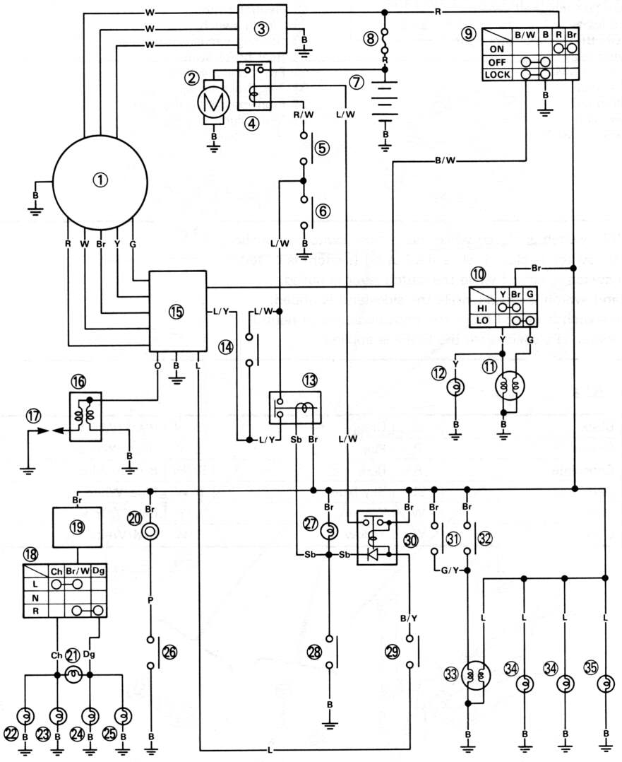
Circuit Diagram Of Xt225

Cdi Ignition
1
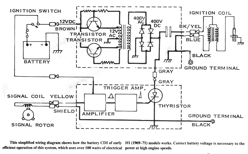
Triple Maintenance Manual

5 Pin Cdi Wiring Diagram Kamboja Sumacher Kultur Im Revier De

335afb2 Dc Cdi Wiring Diagram Timing Trigger Wiring Library
