Dc Motor Controller Diagram Image
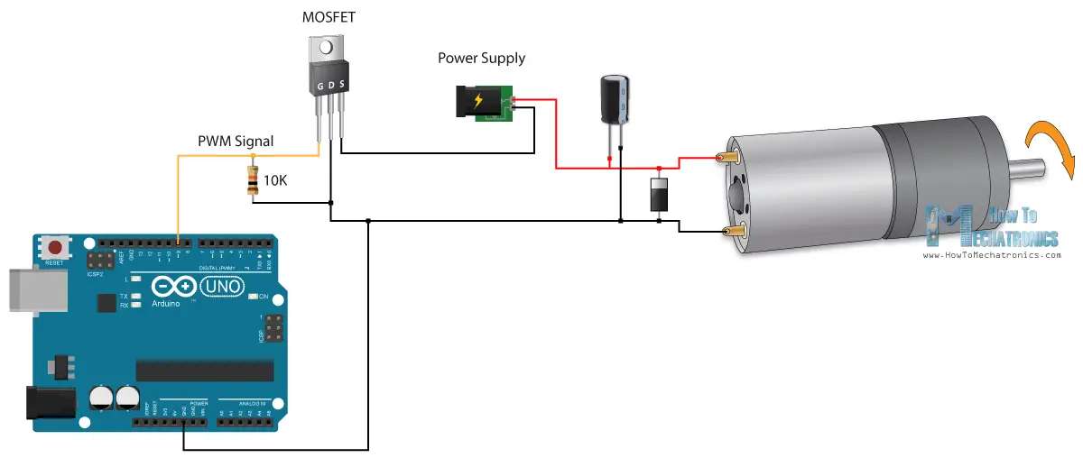
Arduino Dc Motor Control Tutorial L298n Pwm H Bridge

Treadmill Dc Motor Mc 60 Control Ctm Projects

Speed Controlled Two Quadrant Dc Motor Drive Iv Block Diagram
Brushed motors were the first commercially important application of electric power to driving mechanical energy and dc distribution systems were used for more than 100 years to operate motors in commercial and industrial buildings.

Dc motor controller diagram image. Texas instruments equivalent circuit of a dc motor the study of a dc motor and its control involves an accurate analysis of the equivalent model to determine the optimal operating characteristics. One common setup is called the full bridge drive circuit. Wiring a dc motor and universal motor for speed control. Anatomy of a bldc figure 1 is a simplified illustration of bldc motor con struction.
A brushless motor is constructed with a per manent magnet rotor and wire wound stator poles. This drive circuitry is often known as electronic speed controller system or simply an esc. A brushed dc electric motor is an internally commutated electric motor designed to be run from a direct current power source. Pid algorithms is implemented in tuning microcontroller to execute the pwm signal for dc motor drive.
Arduino rpm counter dc motor constant speed controller in this tutorial you will learn how to make an rpm counter and how to automatically adjust the speed of a dc motorin this project the ir sensor will be used with the arduino uno for the rpm measurement and a potentiometervariable resistor will be used to set the rpm value. A 12v namiki dc gear motor is a powerful motor to drive the position control system. And optimized for a pittman n2311a011 brushless dc motor. I am following this controlling dc motors using python with a raspberry pi tutorial but had to modify it slightly to work with a 40 pin.
Connecting first dc motor one. Block diagram of a typical brushless dc motor control or drive system is shown in the following image. Block diagram for dc motor position control. I use a vacuum motor electric lawn mower and treadmill motors to demonstration some cheap options for speed control and wiring to the wall.
Upload the software of the programmable motor controller to the arduino by using the sketch shown next. Other motors were also tested to assure that the code was generally useful. A typical closed loop control system for a three phase bldc motor includes a controller driver and power transistor half bridge h.
35v Dc Motor Controller Pwm Parallax Forums

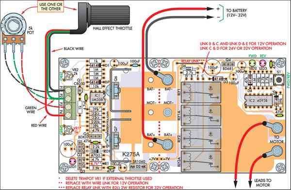
Dc Motor Controller

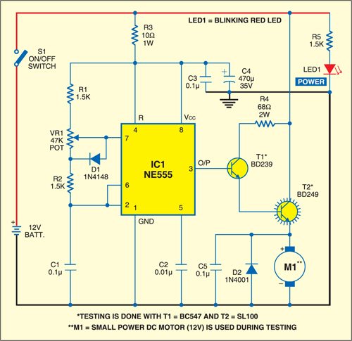
Ne555 Based Pwm Dc Motor Speed Controller Circuit With Pcb Layout
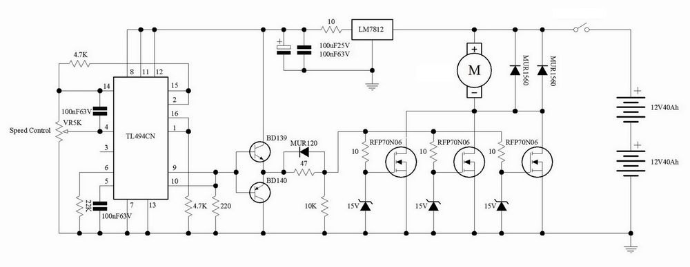
High Power 30a Dc Motor Speed Control Circuit Pwm Lm358 Cd4093

Wa 0219 Pwm Motor Speed Controller Circuit Using Ic556 Electronic
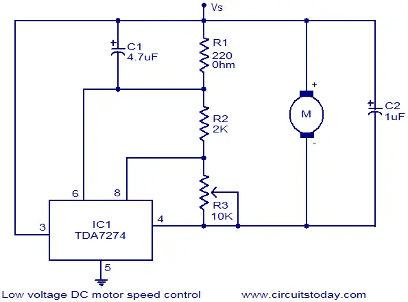
Low Voltage Dc Motor Speed Control Circuit
Dc Motor Speed Control Tutorial Block Diagrams Electronics
Dc Motor Speed Controller Detailed Circuit Diagram Available
Simple Dc Motor Speed Control Circuit Diagram Using Ic 555 Timer
