Electrical Wiring Multiple Schematic

How To Wire A 3 Way Light Switch Family Handyman

Battery Management Wiring Schematics For Typical Applications
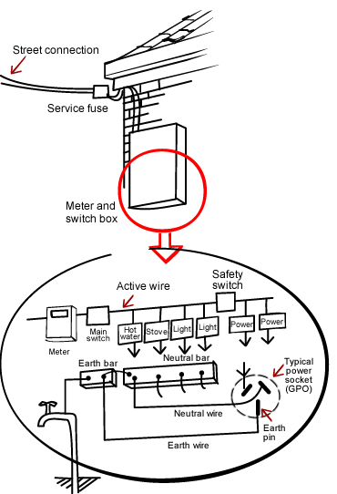
How Are Electrics Installed Build
Multiple terminal symbols in the schematic 1 in the panel i dont know if anyone else has a need to do this but in my regular autocad schematics i can have a terminal symbol show up multiple times but it only references to one terminal in the terminal strip.

Electrical wiring multiple schematic. In today electrical wiring installation tutorial we will show how to wire a three phase consumer unit installation in a multi storey building from utility pole to a 3 phase energy meter 3 phase distribution board and then how to connect single phase three phase loads in a three phase wiring distribution system in home electric supply system. To read electrical schematics the fundamental electrical schematic symbols should be understood. Distribution board is a safe system designed for house or building that included protective devices isolator switches circuit breaker and fuses to connect safely the cables and wires to the sub circuits and final sub circuits including their associated live phase neutral and earth conductors. The uses of these two types of diagrams are compared in table 1.
The prefixes of names are pretty well standardized. If you have multiple resistors in a circuit for example they should be named r 1 r 2 r 3 etc. Component names help us reference specific points in schematics. There are three ways to show electrical circuits.
Use this quiz and worksheet to assess your understanding of electrical schematic symbols. The two most commonly used are the wiring diagram and the schematic diagram. Like comment subscribe all comments will be read and questions answered to the best of the ability of louie vega. A schematic shows the plan and function for an electrical circuit but is not concerned with the physical layout of the wires.
About this quiz worksheet. What is distribution board. They are wiring schematic and pictorial diagrams. See more ideas about electrical wiring diagram electrical wiring diagram.
Wiring diagrams show how the wires are connected and where they should located in the actual device as well as the physical connections between all the components. Then well talk about how those symbols are connected on the schematics. Distribution board is also known as fuse board panel board. Apr 14 2019 explore ppsetiawans board electrical wiring diagram followed by 3823 people on pinterest.
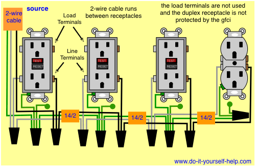
Wiring Diagrams For Gfci Outlets Do It Yourself Help Com

6ee Multiple Schematic Wiring Diagram Electrical Wiring Library
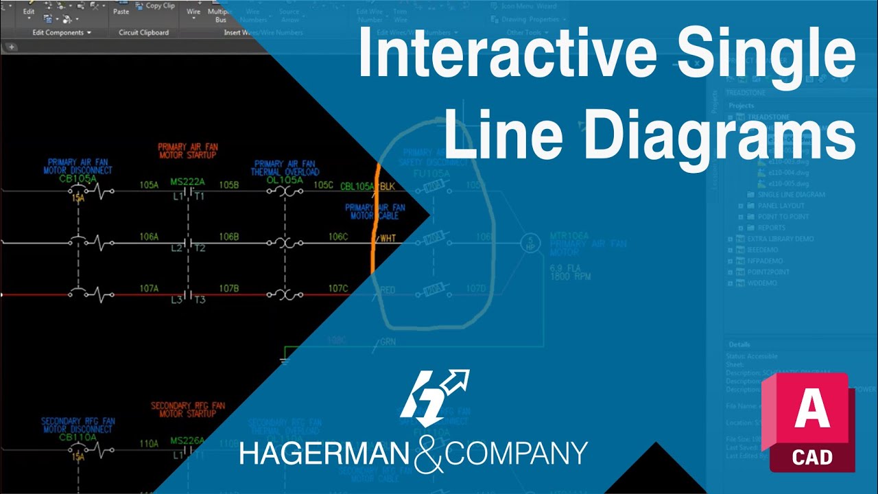
Autocad Electrical Interactive Single Line Diagrams Youtube
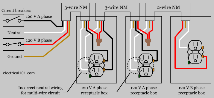
National Electrical Code Multiwire Branch Circuit Transworld

12 Massey Ferguson 165 Wiring Engine Diagram Engine Diagram In

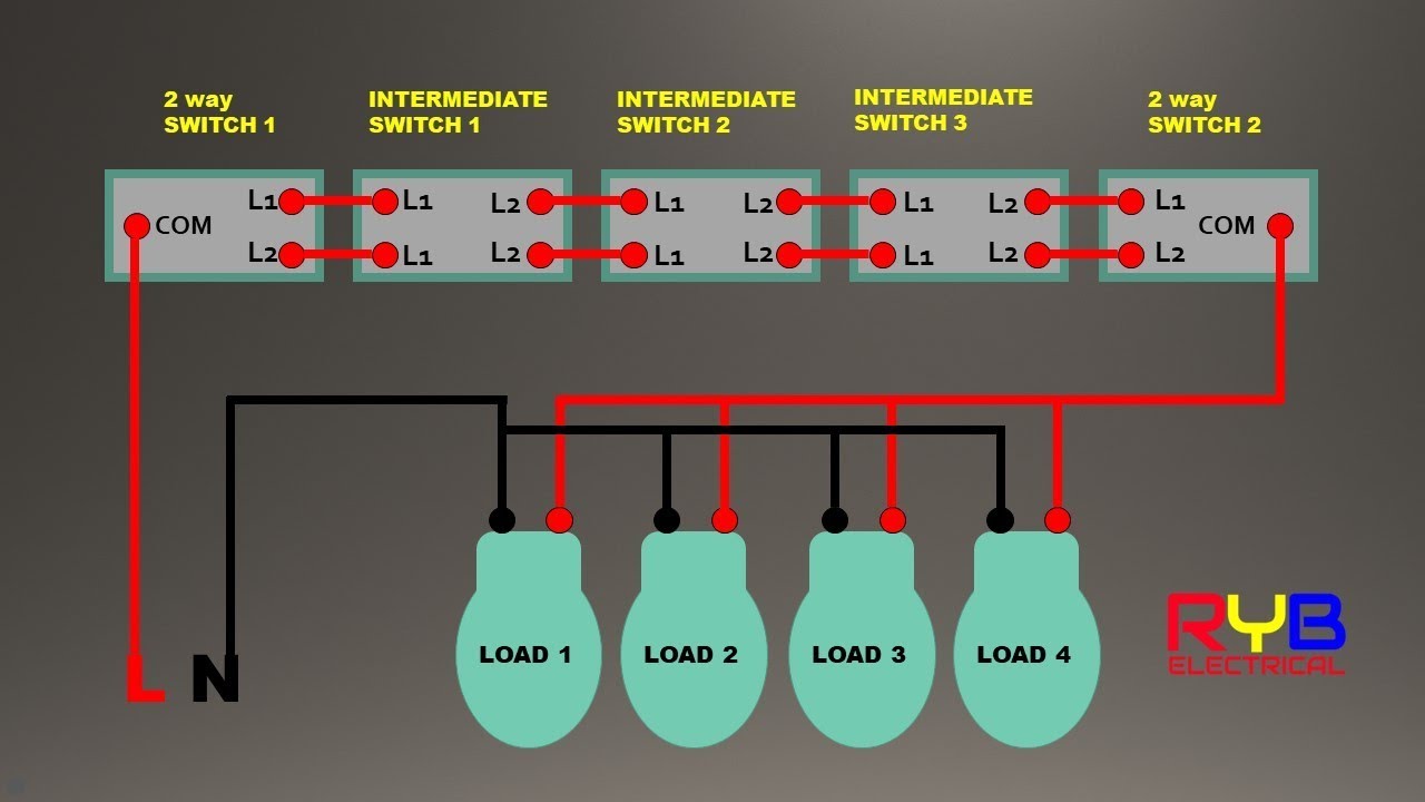
New Wiring Diagrams 3 Way Switch Video On How To Wire A Three In
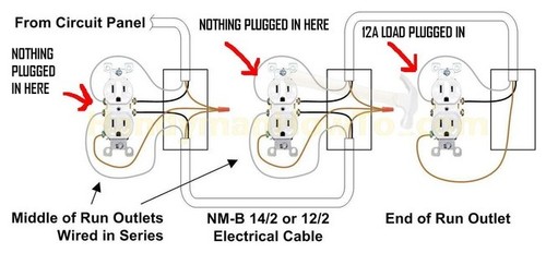
Multiple Outlet Wiring Diagram Wiring Diagram For Multiple

3 Way Switches With Dimmer Wiring Multiple Lights And A 3 Way
Parallel Electrical Wiring Multiple Schematics Wiring Diagram
