Encoder Logic Diagram And Truth Table
Binary Encoders Basics Working Truth Tables Circuit Diagrams
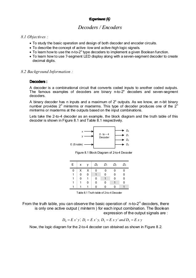
Decoders And Encoders
Encoder In Digital Logic Geeksforgeeks
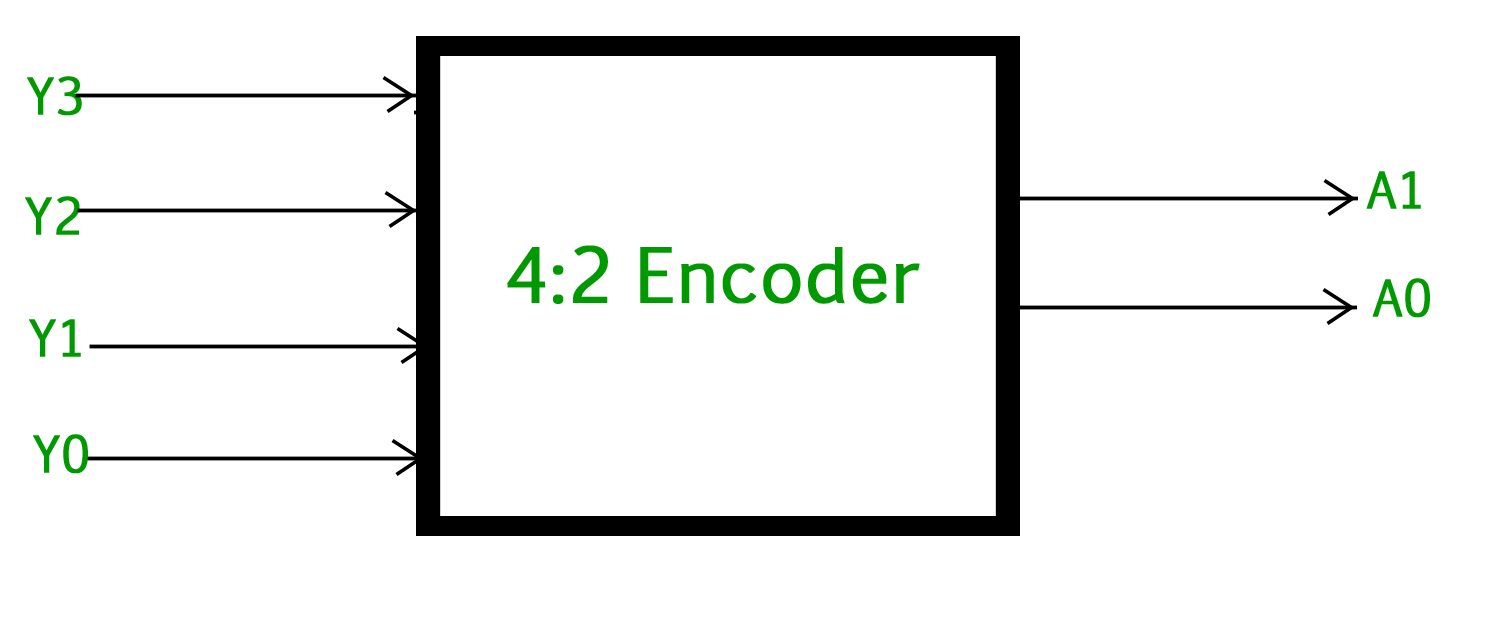
The figure below shows the logic symbol of octal to binary encoder.

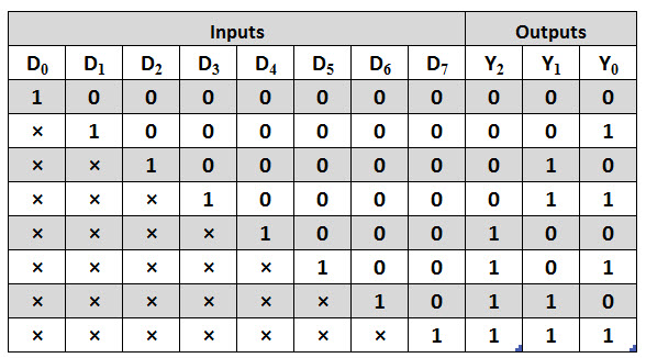
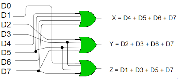
Encoder logic diagram and truth table. There are different types of encoders and decoders like 4 8 and 16 encoders and the truth table of encoder depends upon a particular encoder chosen by the user. It is convenient to use an and gate as the basic decoding element for the output because it produces a high or logic 1 output only when all of its inputs are logic 1. The inputs are represented by x y and z while the compliments are. The truth table for 8 to 3 encoder is as follows.
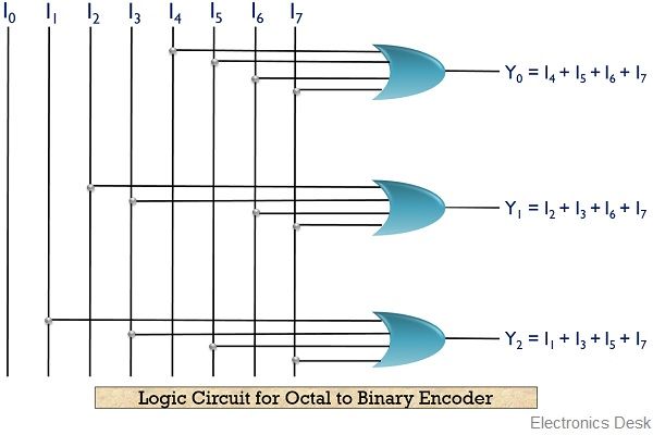
Design 4 x 2 encoder feel free to share this video computer organization and architecture complete video tutorial playlist. Octal to binary encoder is nothing but 8 to 3 encoder. In many circuits this problem is solved by adding sequential logic in order to know not just what input is active but also which order the inputs became active. Each input line corresponds to each octal digit and three outputs generate corresponding binary code.
Y7 to y0 and 3 outputs. The truth table of the encoder is shown below. Here a 4 bit encoder is being explained along with the truth table. A more useful application of combinational encoder design is a binary to 7 segment encoder.
The seven segments are given according to. Httpsgoogl3ly6bl digital electronics complete video. 3 to 8 line decoder has a memory of 8 stages. A2 a1 a0.
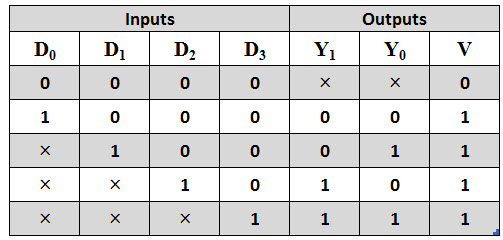
83 encoder truth table. At any time only one of these eight inputs can be 1 in order to get the respective binary code. The truth table of octal to binary encoder is shown below. You can clearly see the logic diagram is developed using the and gates and the not gates.
Truth table of the encoder. The decoders and encoders are designed with logic gate such as an or gate. Since we have thee outputs we will have three expressions as shown below. The block diagram of octal to binary encoder is shown in the following figure.

Building Encoder And Decoder Using Sn 7400 Series Ics De Part 15

Tk 3025 Logic Diagram Of 4 To 2 Encoder Wiring Diagram

Priority Encoder And Digital Encoder Tutorial
What Are Encoders Definition And Type Of Encoders With Truth
Priority Encoder Types With Real Time Applications
Priority Encoder Types With Real Time Applications
Encoders And Decoders In Digital Logic Geeksforgeeks
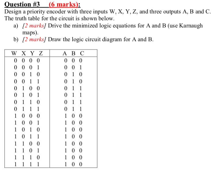
Solved Question 3 6 Marks Design A Priority Encoder W

Fr 2721 Logic Diagram Of 8 To 3 Priority Encoder Free Diagram
