Engine Cooling Fan Relay Diagram
Keep your engine and yourself cool by wiring a switch into your american.
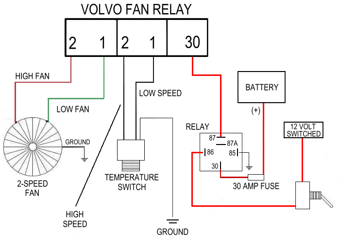
Engine cooling fan relay diagram. Most stand alone adjustable thermostats ie. Hayden flex a lite or perma cool brands can provide a 12 volt output when activated. A cooling fan relay is used on vehicles that have an electrical fan to cool the engine. A relay kit our part number ccfkrl will include everything you need to properly wire up your electric cooling fans with the exception of additional wiring needed to complete all of the circuits.
So today we are going to do the wiring part of the fan. The first part of the installation is to install the electric fan to your radiator and remove the mechanical fan. Since my engine is not stock 1971 riviera 455 cubic inch big block the cooling fan previously that was installed is just not enough to cool it down. Low speed fan relay circuit above these 2 relays is a hydraulic cooling fan module it is not a relay and only applies to 4.
Suggested electric fan wiring diagrams suggested primary cooling fan single speed onoff using 12 volt switching devices only for primary activation note. The function of the cooling fan relay is to convert a low voltage signal from either the electronic control module ecm or a thermostatically controlled sensor. The computer decides whether only one fan is needed or 2 fans depending on engine temperature and ac load have your computer tested its jobs is to energize the appropriate relay as needed. When the correct parameters are met a temperature switch or the computer will activate the relay which will allow power to the fans.
So we have bought a ford taurus 2 speed fan this fan had rumored to cool down the biggest and some of the toughest blocks around. The coolant temperature sensor feeds the computer the engine temperature. A trinary switch will allow your electric fan to turn on and off based on either engine temperature or ac system demand. I have had a lot of people ask me about gm radiator cooling fan diagnosis in the past.
