Engine Manifold Diagram
E4nrp14edoedrm

Schematic Diagram Of A Turbocharged Gasoline Engine Download
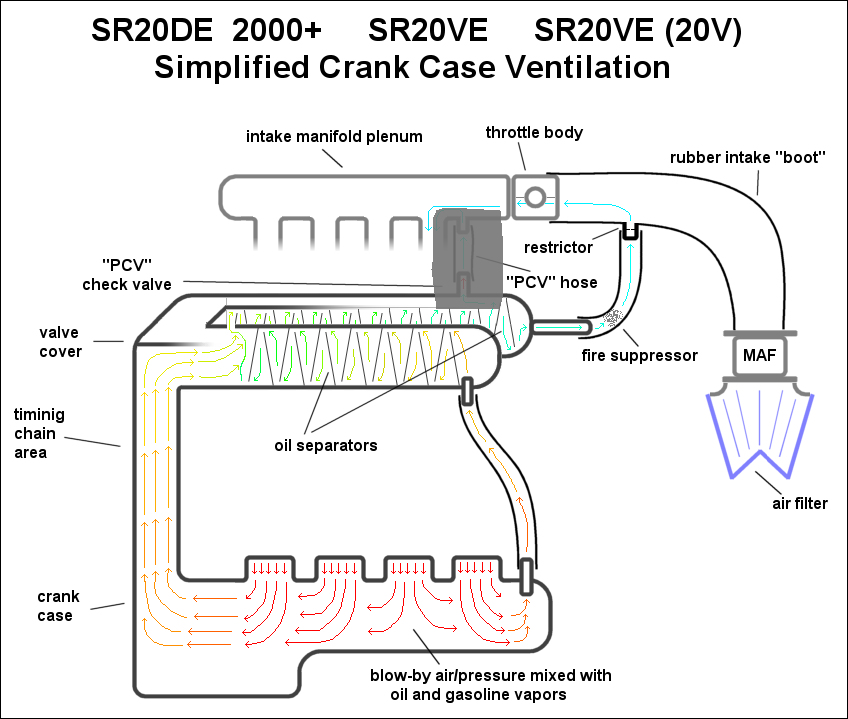
Automotive Crankcase Ventilation Systems Diagram Pcv
The intake air flows through the air filter intake boot snorkel then through the throttle body into the plenum then through the runners and into the cylinders see diagram.
Engine manifold diagram. It is situated between the two cylinder banks on v 8 engines. The ultimate guide ford fe intake manifolds are unique to this engine family and instantly recognizable when compared to any other engines parts. A good design of intake manifold consists of the path from the carburettor to the cylinders as short and short and smooth as possible so that the. Intake manifolds distribute the airfuel mixture to the appropriate cylinders.
The word manifold comes from the old english word manigfeald from the anglo saxon manig many and feald fold and refers to the folding together of multiple inputs and outputs in contrast an inlet or intake manifold supplies air to the cylinders. In automotive engineering an exhaust manifold collects the exhaust gases from multiple cylinders into one pipe. One third of the valve cover extends over the intake casting and the pushrods run through cast or machined passages in the manifold. An intake manifold which is also called inlet manifold is a series of tubes attached to several engine parts as well as to the carburetor if the motor is not fuel injectedthis auto part is not just a passageway for the mixture to flow into but it also contributes to a better distribution.
What is the role and job of the intake manifold. Intake manifold design is geared toward the end usage whether that is a street performance engine or an all out competition application. Ford fe engine intake manifolds.

Engine Arrangement With Integrated Exhaust Manifold Diagram
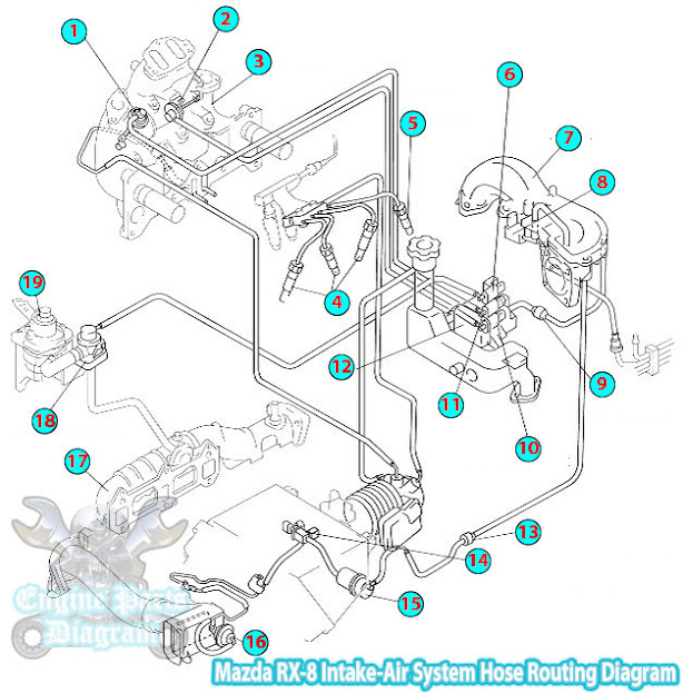
2003 Mazda Rx8 Intake Air System Hose Routing Diagram

Engine Arrangement With Integrated Exhaust Manifold Diagram
Vacuum Diagram I Replaced The Intake Manifold Lower Gaskets
28411 3c610 Genuine Hyundai Gasket Intake Manifold Lh
Intake Manifold And Water Outlet Diagram View Chicago Corvette

F 1 Engine Thrust Chamber
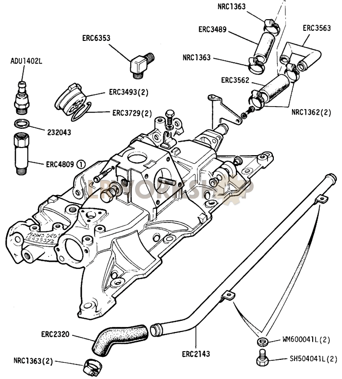
Inlet Manifold Pipes And Hoses 109in V8 Find Land Rover Parts
Buick 3800 Engine Diagram
