F 1 Rocket Engine Diagram

Spacex Its Diagram 01 By William Black On Deviantart

Development Status Of L75 A Brazilian Liquid Propellant Rocket Engine
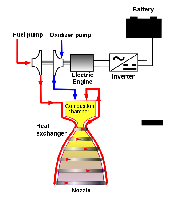
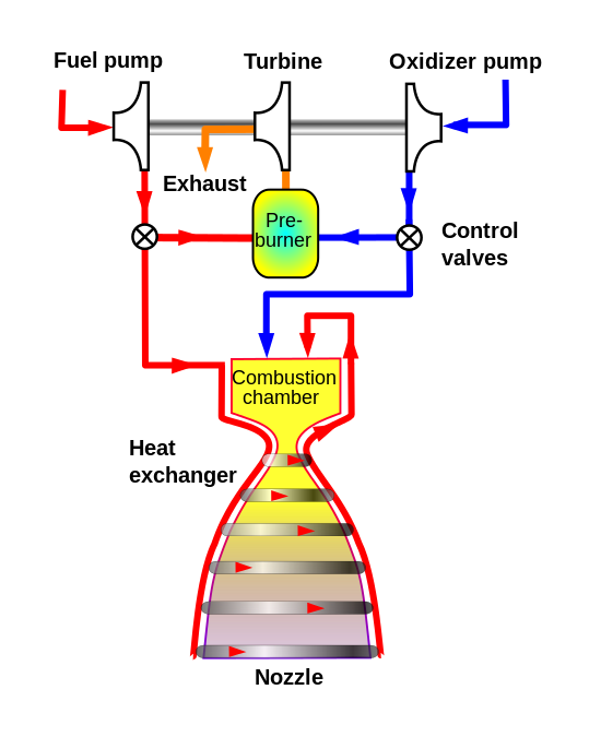
Rocket Propulsion Basic Principles
F 1 liquid fuel rocket engine.
F 1 rocket engine diagram. Rocket engines are reaction engines producing thrust by ejecting mass rearward in accordance with newtons third lawmost rocket engines use the combustion of reactive chemicals to supply the necessary energy but non combusting forms such as. Five f 1 engines were used in the s ic first stage of each saturn v which served as the main launch vehicle of the apollo programthe f 1 remains the most powerful single combustion chamber liquid propellant rocket engine. A rocket engine uses stored rocket propellants as the reaction mass for forming a high speed propulsive jet of fluid usually high temperature gas. In addition to its duties in sustaining proper combustion the injector also played a role in the initial ignition of the engine.
The f 1s propellants rp 1 and lox require an external ignition source to initiate combustion. The thrust chamber is the most recognizable portion of the f 1 rocket engine. Vulcain rocketdyne h 1 wikiwand reference spacecraft engines rl10 amazon goddard rocket engine design graphic t shirt clothing reference spacecraft engines reference spacecraft engines reference spacecraft engines reference spacecraft engines reference spacecraft engines this kind of image f1 rocket engine diagram f 1 rocket engine earlier mentioned can be classed havingplaced through. Image result for merlin rocket engine rocket engine jet engine space rocket.
What others are saying. Diagram of rocket engine diagram of rocket engine diagram of rocket engine welcome for you to the website in this period im going to teach you regarding keyword. 1 2 of the f 1 rocket engine technical manual supplement r 3896 1a adaptation by heroicrelics. This page will deal with the thrust chamber itself.
While the entire thrust chamber assembly consists of a gimbal bearing an oxidizer dome an injector a thrust chamber body a thrust chamber nozzle extension and thermal insulation. This page will additionally refer to the thrust chamber body without its nozzle. F 1 rocket engine thrust chamber diagram. The f 1 engine with 15 million pounds of thrust was the powerplant for the first stage of the 363 foot long saturn v launch vehicle that took the first astronauts to the moon for six successful landing missions.
Through a 28 test qualification program the merlin.

Performance Assessment Of Electrically Driven Pump Fed Lox

Apollo Saturn V F 1 Rocket Engine Blueprint Schematic Saturn V

The Most Powerful Engine Ever Created
Https Www Aulis Com Pdf F 1 Evaluation Pdf
Most Interesting Rocket Engines Erik Engheim Medium

Schematic Of A Symmetric Injector Plate Baffle System Left
Https Link Springer Com Content Pdf 10 1007 2f978 0 387 09630 8 4 Pdf
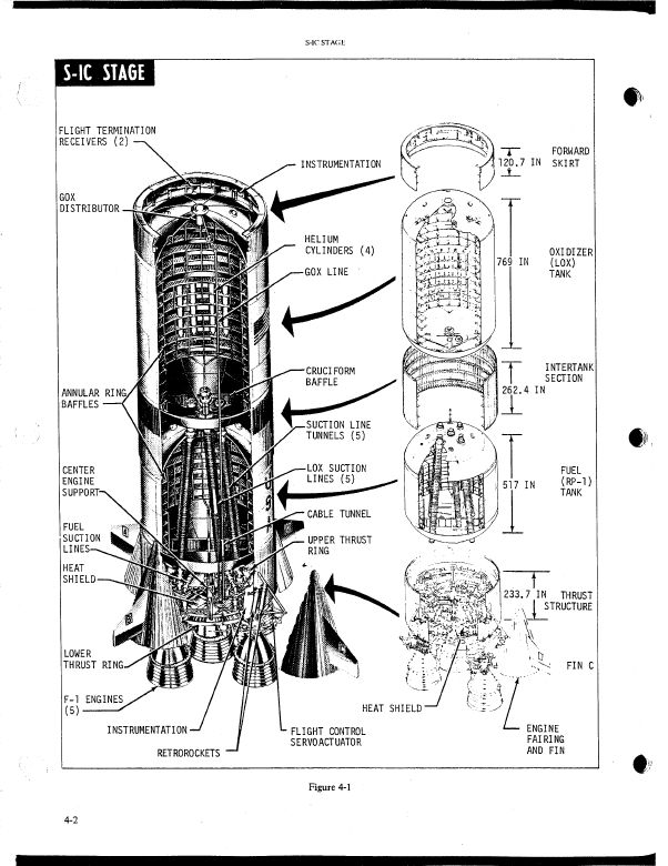
Flight Manual Release Of Huge Rocket Saturn V Used Also In The

Apollo 14 Flight Journal Technical Background Information
