Float Switch Wiring Diagram Heat Pump On
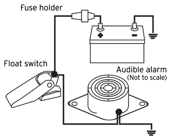
Install A High Water Alarm Trailering Boatus Magazine

Swimming Pool Heat Pump Installation Tips How To Install Best
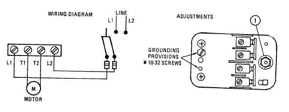
Figure 6 Water Pump Wiring Diagram
In this video our expert nick will walk you through the basics of attaching a vertical float and piggyback tethered style float switch to the.

Float switch wiring diagram heat pump on. Route lead wire into wiring space. A bilge or sump pump has a normally open float switch which turns on the pump when the water level rises above a set point. It reveals the components of the circuit as streamlined shapes as well as the power as well as signal links in between the tools. 3 backlit bilge rocker switch wiring diagram.
A wiring diagram is a streamlined traditional pictorial depiction of an electrical circuit. The information below refers to 115v pumps and wiring. A float switch prevents flooding. In this article we will discuss the correct way to hard wire a float switch to a submersible pump in order to achieve automatic operation.
Internal installation place cpu inside evaporator enclosure or line set cover. Lets start with the most basic float switch. Notice how the heat shrink butt connector is. Variety of septic tank float switch wiring diagram.
Pump products is back with another how to guide. External installation mount cpu to a surface using double sided tape or fasten using a screw. Mount on float switch it is a necessity that you need to mount on your device using some fixing ways of the cable on the well or the tank. Learn more about how our awesome backlit switches work here even that one is still pretty straight forward though here are some diagrams that show the single jumper required on the back of the switch.
Ensure you get some mounting bracket in the float switch which requires a comfortable wedge for fixing the wire in place. A two wire single pole single throw float switchthe rising action of the float can either close ie turn on a normally open circuit or it can open turn off a normally closed circuitinstallation scenarios might include a normally open float switch turning on a pump to empty a tank control schematic 2 or a normally closed. Find your bilge pump float switch wiring diagram here for bilge pump float switch wiring diagram and you can print out. An air conditioner includes a normally closed float switch which turns off the system if the condensate drain clogs and water overfills the drip pan.
Of the three bilge pump switches the only one thats not extremely simple is the backlit automanual bilge pump switch. In this video we are looking at bilge wiring where the positive connection between the bilge pump and the switch is lying right in the bilge water. Wiring diagram for mitsubishi ductless minisplit system fitted with ss610e electronic overflow condensate switch rev a 102012 1.

Star Delta Wiring Diagram System The Engineering Mindset

Hvac Installation Training Basics For Condensate Safety Switches
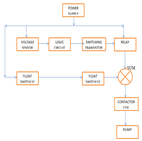
Pump Block Diagram Centrifugal Pump Block Diagram Wire Diagrams

Heat Pumps Explained The Engineering Mindset
Two Wire Control Circuits

Water Pump Wiring Troubleshooting Repair Pump Wiring Diagrams

Condensate Switch Controversy Hvac School

Boat Ac Topics Cruising Aboard Monk36 Trawler Sanctuary

Fh 2318 Rule 750 Pump Wiring Moreover Rule Automatic Bilge Pump
