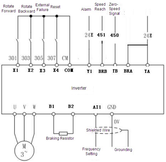
Frequency Converter Wiring Diagram
Voltage To Frequency Converter Using Ujt Simple Circuit Diagram
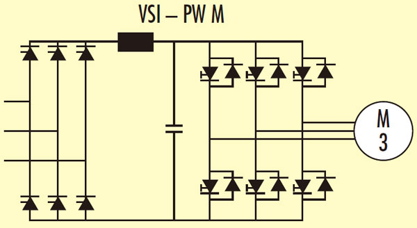
Frequency Converter Basics
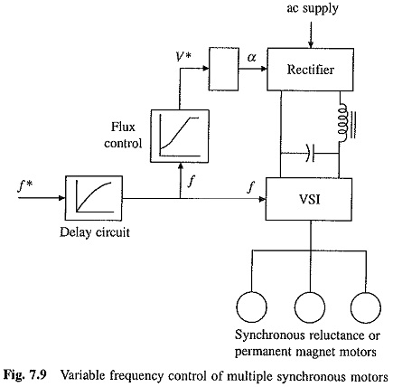
Variable Frequency Control Of Multiple Synchronous Motors
This is a 353 to 107 mhz converter circuit.

Frequency converter wiring diagram. And the output can be between 0 to 10 v. With the switching frequency equaling about 3 khz and with an igbt of the second generation. The circuit works according to a simple principle. A converter has always a mixer and an oscillator.
Top single phase to 3 phase converter circuit diagram hp03. The curves are representative for frequency converters in the power range of 50300 kw. Using the values given on the diagram the circuit oscillates at 46 mhz. The width of the impulses depend on r4 p1 and c1.
In figure 1 ic1 act as the frequency generator is controlled by voltage. Line filter limits electric interferences into the public power supply network and improves the electromagnetic. Uses minimum number of components and almost all components required for this circuit can be obtained from your scrap box. Click on the image to enlarge and then save it to your computer by right clicking on the image.
3 phase rotary converter wiring diagram. This voltage to frequency converter circuit has an oscillator that is voltage controlled and has a small 05 deviation. The diagram below shows the basic circuit of frequency to voltage converter using op amp and rc networks. The input frequency given to this converter can be in the range of 0 10 khz.
Frequency to voltage converter using ne555. Its amplifier component can then be used as the oscillator by adding an lc network to it l1c1. The 8 pin dip ic can work in a wide range of bandwidth from 1hz to 100 khz. It also has a wide range of supply voltage from 5v to 40v.
This is one great application of ne555 timer ic. It converts the 353 mhz signal coming from a vhfuhf tuner down to an fm tuner to decode the tv audio in fm quality. Frequency converter block diagram ac line voltage 3 x 400 500 v ac 50 60 hz. A very simple and cheap f to v converter tha operates from 12vdc.
This voltage to frequency converter circuit use the ca3130 op amp ics that linearity of changing is very well up to 05 and temperature coefficient of less than 001 per degree celsius. Ic1 function as a multivibrator and produces rectangular impulses with equal width. Following figure shows the frequency converter efficiency as function of the frequency at a cubic load for units rated at 45 90 and 260 kw. The tba120 can be used as the mixer.
With p1 we can do fine adjustments of the output frequency.

Voltage To Frequency Converter Circuit Diagram In 2020 Circuit

50hz 60hz Frequency Generator Circuit Using Crystal Oscillator

Wind Power Converter Wiring Diagram Since The Switching Frequency
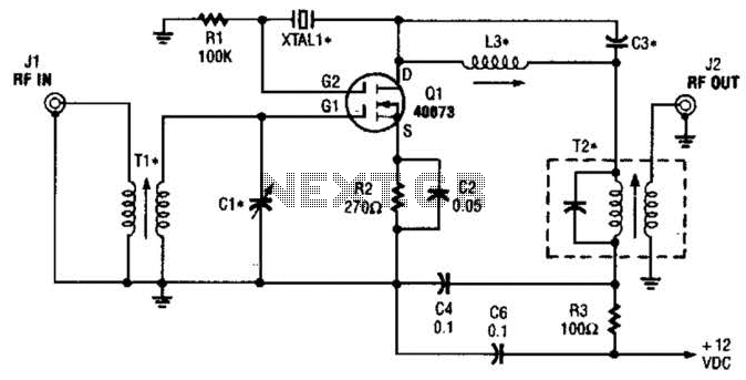
Crystal Controlled Frequency Converter Circuit Under Rf Converter
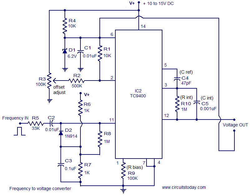
Frequency To Voltage Converter Circuit Based On The Tc9400 Ic

Cs 1111 Frequency Converter Circuit Schematic Download Diagram
2113 Motor Speed Control For 3 Phase Induction Motors Dr
Frequency Inverter

Voltage Controlled Oscillator Wikipedia
