Function Block Diagram Plc Logic Diagram

Ladder Diagram Function Block Diagram Lad Fbd Industry Mall

Plc Programming Function Block Diagram Instruction List And

Plc Programming Plc Manual
Plc designers introduced specialised intelligent units for the various tasks to be carried out by logic controllers but multiprocessing still greatly increases the complexity of system programming.

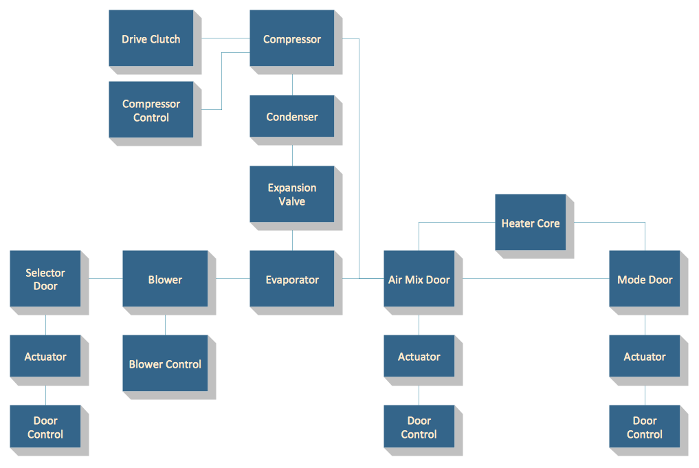
Function block diagram plc logic diagram. In a function block diagram the entire rung is replaced by this box or block. One of the official and widely used plc programming languages is the function block diagram fbd. The function block diagram fbd is a graphical language for programmable logic controller design that can describe the function between input variables and output variables. A function block is a program instruction unit that when executed yields one or more output values.
It is described as a graphical language for depicting signal and data flows through blocks which are reusable software elements. Guidance on selection installation and maintenance of plcs. Fbd is a graphical language in which you deal with the blocks and connection between. The connecting lines will have a compatible information type at both ends.
I first encountered function block diagrams working in a tire manufacturing plant about 12 years ago. Input and output variables are connected to blocks by connection lines. A fbd program is built using function blocks connected together to define the data exchange. In this video you will learn the basics of programming plcs with function block diagramming fbd language.
A function is described as a set of elementary blocks. A functional block diagram describes a function between input and output through a functional block. List of major changes and extensions of the third edition. Formal specification of the language elements.
Inputs and outputs of the blocks are wired together with connection lines or links. You will understand the working principle of plc from the block diagram of plcplc stands for programmable logic controllernowadays plc becomes more and more popular in industries for automation purpose. The term function block diagram fbd is used for plc programs described in terms of graphical blocks. 2 overview of the function block diagram language.
A complete function block diagram will utilize many more function blocks and possibly even combinations of several blocks. It is a simple and graphical way to program any functions together in a plc program. Graphic languages ladder diagram and function block diagram annex a. Many industrial machine use and logic.

Controllogix Function Block Diagram

Figure 2 From A 3 6 Ns Ecl Field Programmable Array Logic Device

Siemens S7 300400 Plc Ladder Diagram And Function Block Diagram

Programmable Logic Controllers Plcs Basics Types
1

Control Fpwin Pro7 Panasonic Industrial Devices
Functional Block Diagram

What Is The Difference Between Ladder Logic And Function Block
.gif)
Expansion Modules Siemens Logo Easy Relay Smart Relay Mini Plc
