Ge 3 Wire Control Schematic
Wire line voltage the load circuits are shorted.

Ge 3 wire control schematic. See image below for an example of 3 wire control being used to pull in a contactor to start a 3 phase motor. A second pulse on alternate leg returns contactor to original state 2 wire control is the choice for single output automatic operation or for operation from single pole devices. Wiring diagram yamaha f115tlrb archives ipphil new wiring. A wiring diagram mini manual is included with each appliance.
Skip navigation sign. Page 56 quick checks dead unit. 2 wire control is used for single location control with power continuously supplied to thecoil for contactor operation. Make sure that all line and low voltage wiring is confined to the appropriate areas.
How to obtain a wiring diagram or schematic. Of cables range of wire sizes 3 14 to 10 awg 3 14 to 10 awg 3 6 awg to 350 mcm 3 6 awg to 350 mcm 4 4 awg to 600 mcm 260 1 6 awg to 350 mcm 3 6 awg to 350 mcm 8 4 awg to 600 mcm 12 4 awg to 600 mcm 1600 2000 2600 3000 8 2 awg to 600 mcm 24 4 awg to 600 mcm engine start control connections engine startcontrol. Page 10 the 3 position manual vent door control may the ge zoneline 2800 series with the dry air 25 heat be closed. 3 wire control is the choice for use with momentary devices allowing operation from multiple locations a momentary pulse of energy operates contactor.
Ge zoneline generation 3 2800 series service manual. Connect power supply ground wire to the hole in tub using green 8 32 screw figure 3. When you press the start button and the stop button is not pressed the 24vdc relay energizes and it pulls in the r1 contactor that feeds three phase power to the motor. In this video i demonstrate a 3 wire startstop circuit.
The contactor is operated from a momentary pilot device and requires an auxiliary contact tobe used as a holding interlock. Checking from either wire on terminal of capacitor to the black wire on ry101 will check the overload and common. 3 wire control is typically used when control is desired from multiple locations. 3 14 to 10 awg no.
The most common use of 3 wire control is a startstop control. This video walks you through the basic 2 wire and 3 wire control for 3 phase motor controllers. Samsung wa6500b5 washing machine motor buzzes doityourself. I describe each of the components involved such as the motor starter overload start pushbutton stop pushbutton and control power and.
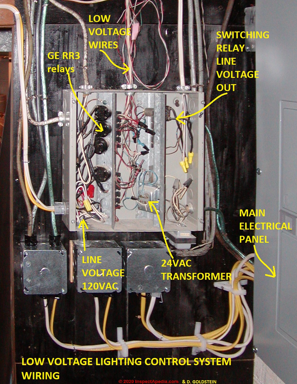
Wire from the circuit breaker through each relays spst output terminals and from there to the loads. If you are in need of a replacement wiring diagram you can determine where to find it on your appliance by visiting. 3 wire washing machine motor wiring diagram sample how to wire up a washing machine motor.


