Gm Amp Gauge Alternator Wiring

Gm Regulator Wiring Wiring Diagram
5 Common Causes Of Your Alternator Not Charging And How To Fix
Alternator Upgrade Wiring Tips For Popular Gm Charging Systems
Amp gauge wiring 1 always disconnect the ground lead from the vehicle battery before wiring any gauge.

Gm amp gauge alternator wiring. 64 72 charging system wire up using gm 3 wire internally regulated alternator. Wiring an alternator. Other side of amp gauge goes to ignition switch headlight switch ie. Thru amp gauge to the battery or starter post.
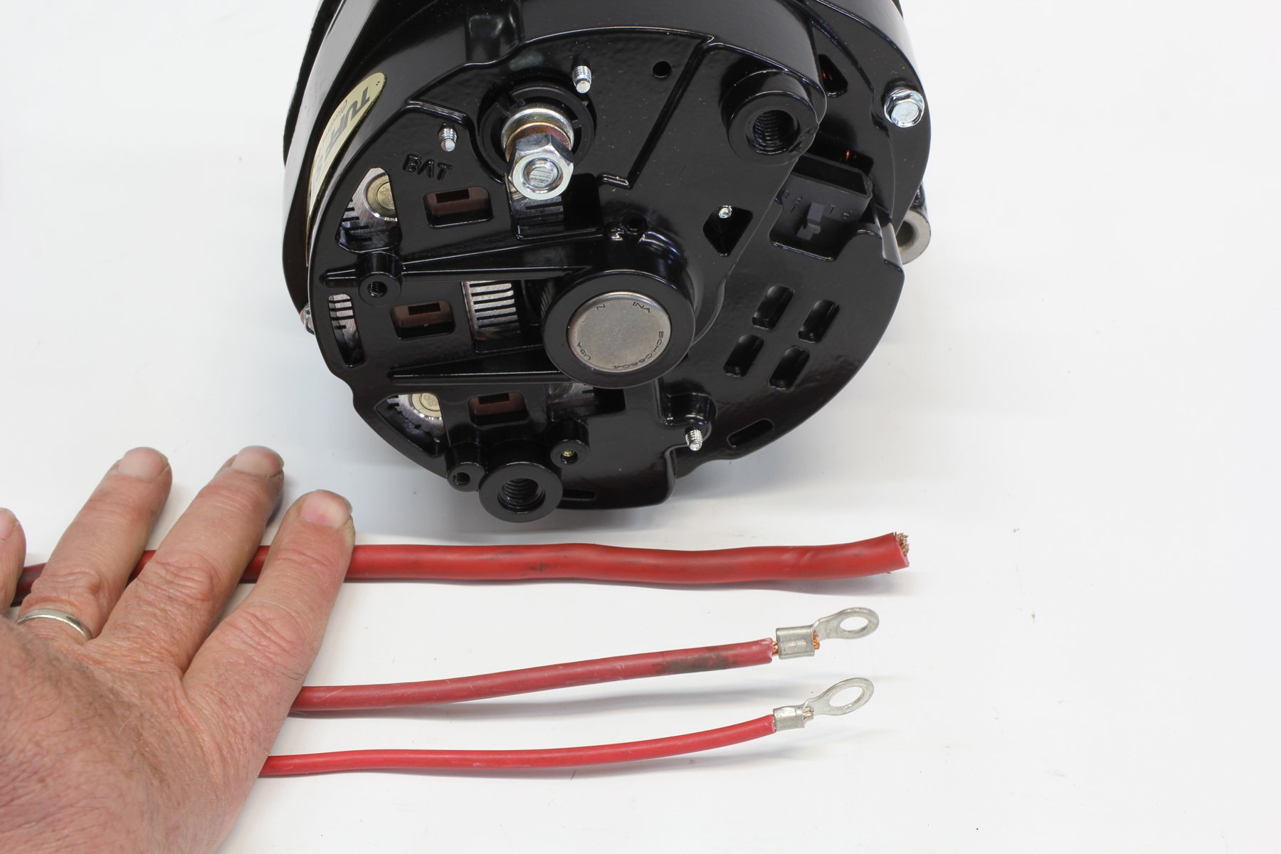
This diagram shows how to wire a delco gm internally regulated 3 wire alternatorthis particular model 10si used in the 1970s and early 80s is the one youll find on the generation of gm cars most often used in demolition derbies. Chris craft 191538 views. The amp gauge needs to see full amperage from the alternator so the wire runs from alt. This alternator 10 dn uses a flat two prong connection at the back of the alternator.
The original 1960s gm alternator employs an external voltage regulator. All possible loads and also the heavy gauge wire from the stud on alternator. Chris craft 1735491 views. Major 140 amp alternator upgrade.
The least expensive upgrade from the 10 dn would be to step up to a 10 si or 12 si. The easy way to do that is to wire a gauge for your alternator which is called an voltmeter. Gm 1 wire 100 amp alternator upgrade and info diy duration. But to get the voltage coming out of the alternator you really have to connect the voltmeter to the battery and therefore the ignition wiring in the vehicle since thats what the alternator is feeding.
Below are a few of the top drawings we obtain from different sources we wish these pictures will certainly be useful to you and hopefully very appropriate to just what you want about the 3 wire gm alternator wiring is. Remove the alternator mounting bolt with an appropriately sized socket wrench and separate the alternator from the vehicles body about 14 inch. Add no wires between the amp gauge and alt that draw current or the guage will not show correct amperage. Alternator demo wiring connection to.
The gauge should have two posts one in one out. The other main connection on the alternator is the output terminal that charges the battery. Auto meter american muscle gauge. Position your newly crimped wire terminal between the vehicle body and the alternator mount.
2 classic instruments amp gauge should only be used on vehicles with alternators rated at 60 amps or less. 800 x 600 px source. Terminal 1 should be exciter or field terminal and should be run through a diode to the ignition terminal or to the ignition switch side of the ballast resistor. Crimp a round wire terminal onto the end of the black negative wire coming from your amp gauge.
That wire should be at least 12 gauge.
Single Wire Alternator Need Wiring Help The 1947 Present

1949 1954 Desoto 6 Volt To 12 Volt Conversion Kit Vintage Auto

Alternator Gauge Wiring Diagram Pandemi Www Thedotproject Co
Electrical Solutions For Small Engines And Garden Pulling

Sl 5417 Amp Meter Wiring Diagram 1966 Mustang Ammeter Wiring Ford

Bb 6960 Wiring Diagram 12 Volt Alternator Wiring Gm 10si

How To Solve The Camaro Amp Gauge Mystery Without Tears

3 Ways To Install A Car Volt Amp Gauge Wikihow

Easy Installing Of A Car Volt Amp Gauge Youtube
