Goodman Heat Pump Wiring Diagram 6 Wire
What All Those Letters Mean On Your Thermostat S Wiring Ifixit

Wiring Thermostat To Furnace Board Schematic Diagram
How To Wire A Thermostat Wiring Installation Instructions Guide
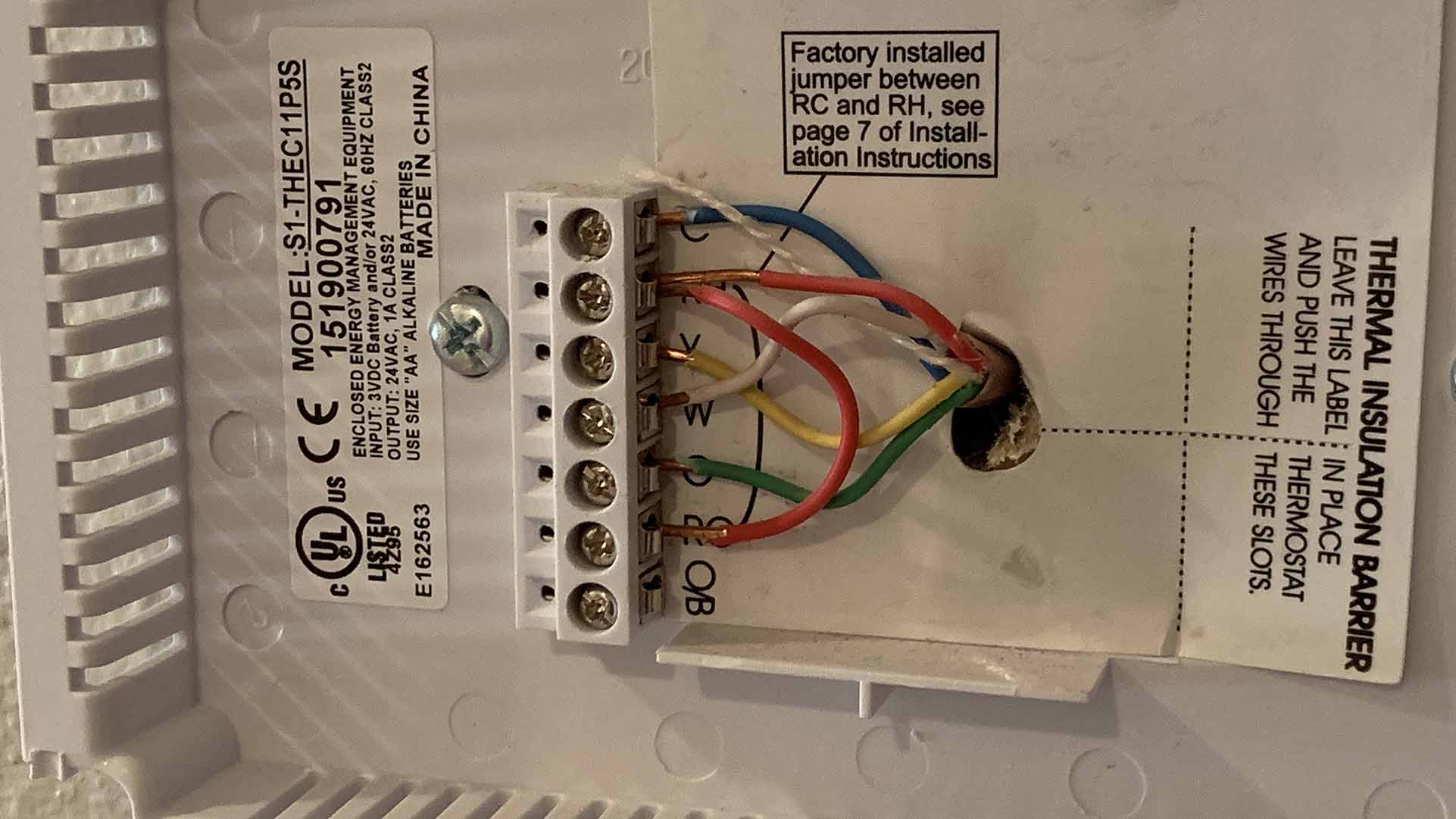
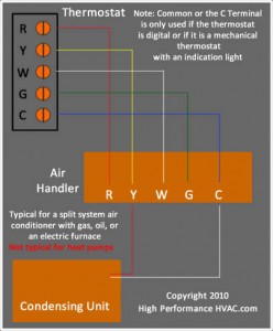
Y yellow is compressor g green for fan.
Goodman heat pump wiring diagram 6 wire. Route control wires through the low volt age port and terminate in accordance with the wiring diagram indoor provided inside the control panel cover. Low voltage is the voltage that is used to control the unit from a thermostat or other controlling device. These two sources are high voltage and low voltage. The typical aspects in a wiring diagram are ground power supply wire and connection result devices switches resistors reasoning entrance lights and so on.
Always follow manufacturers instructions for both the thermostat and the hvac system. The color of wire r is usually red and c is black. As shown in the diagram you will need to power up the thermostat and the 24v ac power is connected to the r and c terminals. Goodman heat pump package unit wiring diagram gallery.
Additional articles on this site concerning thermostats and wiring can help you solve your problem or correctly wire a new thermostat. Goodman heatpump like to no how i can wire it to my thermostat in my house thehow do i wire a honeywell pro tstat 188 wire to a goodman model xxxxx i have a 5 wire stat and the reverse valve does not operate w present stat. Heat pump thermostat wiring chart diagram hvac the following graphics are meant as a guide only. A listing of electric signs and also summaries could be located on the electric sign web page.
Goodman aruf air handler wiring diagram luxury bard heat pump wiring a novice s overview of circuit diagrams a first check out a circuit representation might be confusing however if you could check out a subway map you could read schematics. R red is hot 24 volts o orange reversing valve w white is heat. Collection of goodman heat pump wiring diagram thermostat. A wiring diagram is a simplified traditional pictorial representation of an electrical circuit.
It shows the components of the circuit as streamlined forms as well as the power as well as signal links in between the tools. C is known as the common terminal. Looking at t stat the wiring diagram is set up for either conventional or heat pump if looking at. Here i am telling what each terminal if for.
Heat pump thermostat wiring a typical wire color and terminal diagram. In the goodman heat pump there are two wiring sources that have to be connected.
How Wire A Honeywell Room Thermostat Honeywell Thermostat Wiring
Goodman Wiring Diagram Hamra Arabians De

Heat Pump Thermostat Wiring Chart Diagram Easy Step By Step

Heat Pump Low Voltage Wiring Diagram Wiring Diagram

Replacing A Goodman Janitrol Hpt 18 60 Thermostat Doityourself
I Need Help Wiring A Nest Thermostat To A Goodman Furnace

Goodman Pcbdm133sappliance Replacement Partsgoodman Defrost

Wiring Of A Single Stage Heat Pump Youtube

Package Ac Wiring Diagram Lair Lan1 Afcev De
