High Control Wiring Diagram For Alarm
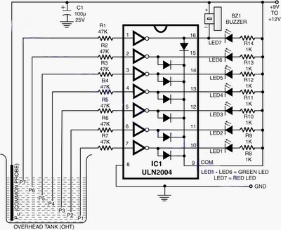
Water Level Indicator Circuit Working And Its Applications

Motion Detector Alarm Circuit
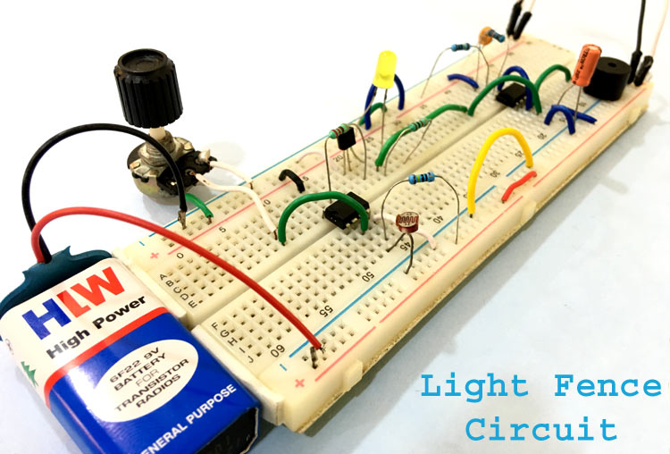
Automatic Light Fence Circuit Diagram With Alarm
Internal relay configuration 12v.
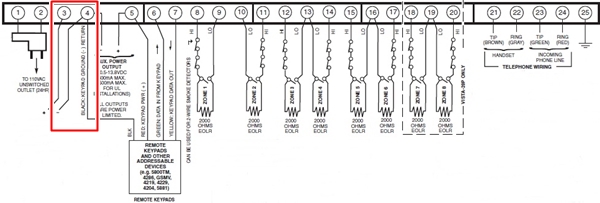
High control wiring diagram for alarm. How to reset all ecus and control modules in your car or truck. On the bottom line you have the wiring terminals for the switches providing hysteresis wires 1 2. You can connect your wired siren to the konnected device using the relay included in our kit or with a relay purchased separately see our buying guide for suggestions. 446 security system pdf manual download.
The circuit will warn us for any temperature higher than default setting which already predefined before. Use proper grounding and handling procedures to prevent permanent damage to this device. Wiring a siren strobe or sounder most wired alarm system installations have a an audible siren that activates in the home when an intrusion is detected. This is the circuit design of high temperature alarm system.
To plugging control module in. For most of us this wont suffice since most well pumps are 1 hp or larger. But a bz1 buzzer also can not emit sound since q1 transistor also not working which the controller section not is connecting together. As with the seal in relay above the wiring necessary for the alarm contact will vary based on your control equipment.
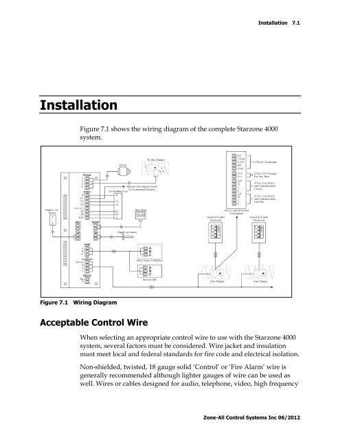
Wires from speaker siren horn lock nc violet wire pin 13 14 15 rev. Using the wiring diagram provided with the control make the wiring connections to the delta p control the solid state timer and the solenoid valves. A wiring diagram is a simplified conventional pictorial depiction of an electrical circuit. 2 page autowatch 446 rlc alarm wiring diagram dpfk 695522 1 of 5 01.
Fire alarm system is the combination of different components such as smoke detector heat detector carbon monoxide detector multi sensor detector call points sounders bells relay module repeater annunciator fire control panel and other related and optional security devices designed for fire alarm control system. Temperature control is done by the thermistor th1 which is a negative factor. It shows the parts of the circuit as streamlined shapes as well as the power as well as signal connections in between the gadgets. Sump alarm 2359 and 2368 series 3 wire float switches are rated for direct control of pumps up to 12 hp or 13 amps at 120 or 240 vac for non continuous operation of the pump.
Make the required connections to the motor starters low voltage terminals. Variety of fire alarm installation wiring diagram. The high pressure sensor is connected to the other sensor voltage. Pressure sensor wiring diagram amazon printed.

Electricveda Com Fire Alarm System In Electrical Construction Works
Vista 20p Installation Guide
High Control Wiring Diagrams For Alarms Wiring Diagram

Lm8560 Digital Clock Circuit Diagram With Alarm Eleccircuit Com

Wiring Fire Alarm Systems Throughout Burglar Diagram Pdf In For

48 72v Brushless Controller Wiring Diagram Please Help
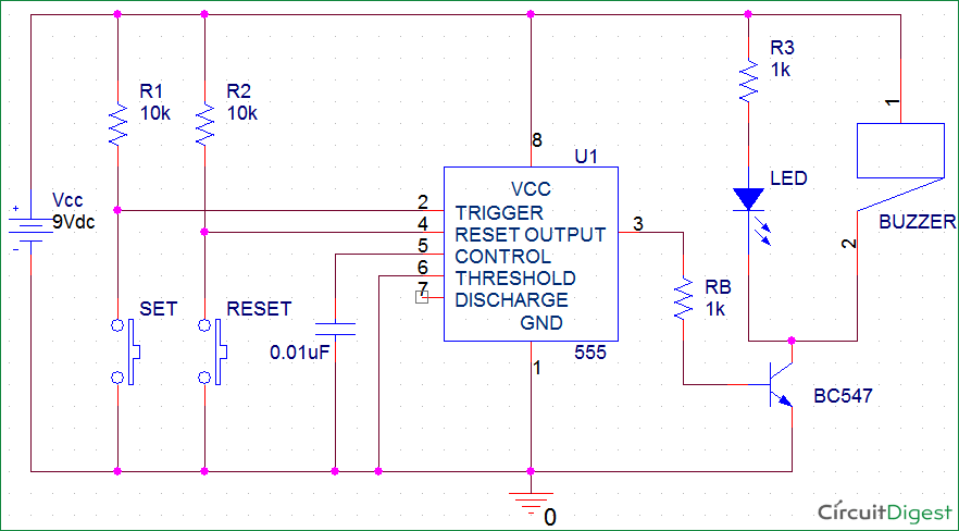
Panic Alarm Circuit Diagram Using 555 Timer Ic

Emerson Exchange 365

Tl 0173 Home Alarm System Wiring Diagram As Well Fire Alarm Riser
