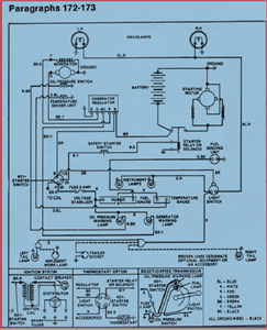
Hvac Electrical Wiring Diagram N8mpn
Installing your low voltage two wire is very simple to do on an air conditioning condensing unit.
Hvac electrical wiring diagram n8mpn. How to wire an air conditioner for control 5 wires the diagram below includes the typical control wiring for a conventional central air conditioning systemfurthermore it includes a thermostat a condenser and an air handler with a heat source. It reveals the components of the circuit as simplified shapes and also the power and also signal connections between the gadgets. Piece of hvacr equipment the problem tur ns out to be electrical in nature. Wiring diagram notes 1.
571 x 519 px source. If you have a clear under standing of how to read wiring diagrams you fre quently can find the source of the trouble simply by checking the wiring of the unit itself against the man ufacturers wiring diagramthe purpose of this chap. How to wire an air conditioner for control 5 wires thermostat wiring diagram size. A wiring diagram is a simplified conventional photographic depiction of an electrical circuit.
Wiring diagram n8mpnl 8mpnl 441 01 2613 06 specifications are subject to change without notice. The heat source for a basic ac system can include heat strips for electric heat or even a hot water coil inside the air handler that is fed from a water heater. Air conditioning unit wiring diagrams fig. Number 006 024 winter start 4 evaporator defrost thermostat 5 temp.
Do not try any of what you see in this video at home. 138ck018 32 34 38ckm024 32 34 38ck. Below are some of the top illustrations we obtain from various sources we wish these images will certainly work to you as well as with any luck really pertinent to what you desire about the trane air conditioner wiring diagram is. I demonstrate how easy it is to use the wiring diagram to figure out where the wires go.
Moreover the heat source for a basic ac system can include heat strips for electric heat or even a hot water coil inside the. Symbols are electrical representations only. Wiring diagrams index unit 50byn v ph hz label diagram fig. Hvac thermostat wiring diagram lovely wonderful carrier heating.
Compressor and fan motor furnished with inherent thermal. Page 44 inducedcombustion gas furnace parts replacement information guide casing group filter group flame sensor hot surface ignitor outer door filters washable 1in. In this hvac video i show you how to understand the schematic and connection diagrams for troubleshooting electrical wiring faults inside hvac units. It takes at least two years of hvacr.
Number 006 008 208230 3 60 460 3 60 11720011 c 1 575 3 60 012 208230 3 60 014 460 3 60 11720960 b 2 016 575 3 60 024 208230 3 60 460 3 60 1172007 c 3 575 3 60 accessory wiring unit 50byn accessory description fig.
