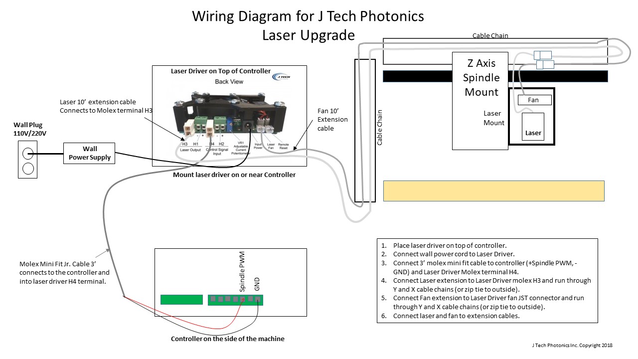
Laser Wire Diagram
3018 laser wiring diagram if you need english manual pls leave me your e mail we would sent it to you with er11 diy mini cnc laser engraving machine kits 3 axis acrylic pcb.

Laser wire diagram. I have a cnc chinese cheap model it runs off grbl the motherboard says woodpecker cnc or if you want to control the motor speed and utilize the internal circuit of your existing system i think. A laser diode driver circuit is a circuit which is used to limit the current and then supplies to the laser diode so it can work properly. The performance of coding solutions in wire cable and pipe industries needs to match the realities of the production process. A laser diode is a diode which outputs a laser beam.
Uv laser wire marking. Laser diode driver circuit. Laser transceiver schematics wiring diagram circuits schema electronic projects shema laser transmitterreceiver lazer tag equipment modifications schematics wiring diagram circuits schema electronic projects shema. Coder downtime that stops the extrusion process can result in expensive downtime rework and scrap.
Enjoy the videos and music you love upload original content and share it all with friends family and the world on youtube. If we directly connect it to the supply due to more current it will damage. In this project we will show how to connect up and build a laser diode circuit. The correct way to fix a leaking joint unsoldering got2learn duration.
Poor code contrast or quality and ink transference are further challenges that can degrade the quality of your product. Co2 laser power supply wiring diagram download here it is compatible with most of chinese other brands co2 laser power supply. A wiring diagram is a streamlined conventional photographic representation of an electric circuit. Uv laser wire marking was originally developed in 1987 by spectrum researchers to meet the needs of the international aerospace industry for a means of safely applying permanent identity codes to non stick ptfeteflon and similar wire insulations as well as fibre optics.
Assortment of exmark lazer z wiring schematic. It shows the elements of the circuit as simplified shapes as well as the power and signal links between the devices.