Logic Diagram Network

Binary Decoder Circuit Diagram 1 Aus N Decoder Electrical Network
Virtual Circuit Network Encyclopedia

Logic Network Diagram Dnv Gl Software
A network diagram can be either physical or logical.
Logic diagram network. Network diagrams both logical and physical are key to effective network and it infrastructure management. Therefore logical network diagrams typically show subnets including vlan ids masks and addresses network devices like routers and firewalls and routing protocols. Stencils in a logical diagram should be obviously logical representations of the network nodes. Specifically the projects specific network logic as dictated and pre determined by the project management team and or the project management team leader refers to and represents the particular collection of schedule activity dependencies that exists for the purpose of making up the entirety of the project schedule network diagram.
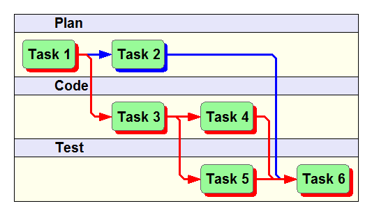
A logic network shows the sequence of activities in a project across time. A logical network diagram displays how information flows through a network allowing you to see subnets network devices and routing protocols. This visual representation helps to keep your network optimized. Logical network diagram network and peripherals.
The biggest single problem im seeing when working on enterprise networks is the lack of l3 logical network diagrams. Examples of logical network diagram the logical network diagram will be used to represent how you network connections are using the upper layer of the osi and will help to understand your ip addressing. L3 diagrams are vital for troubleshooting or for planning changes. With up to date diagrams network admins can troubleshoot and minimize downtime plan for capacity avoid it clutter maintain software and keep the network secure and compliantthere are two main types of network diagrams.
Project scheduling pertcpm finding critical path duration. Keeping that in mind i propose that it doesnt make sense to use a physical network device stencil which is essentially a picture of the actual device with ports fans rack ears in a logical diagram. Also logical diagrams are in many cases more valuable than. Finish to finish ff network diagram example with lag duration.
The logic gate software has all the logic symbols you need to design any kind of logic model. It indicates which activity logically precedes or follows another. Logical network diagram computers and monitors. Most of the time im facing situations where a customer doesnt have any logical network diagrams to give.
Easily create a diagram using the logical network diagram template above by signing up for a free lucidchart account and then styling the diagram with our different formatting options.

Network Diagram Examples And Templates Lucidchart

Binary Decoder Circuit Diagram 1 Aus N Decoder Electrical Network

Markov Logic Network Based Complex Event Detection Under Uncertainty

Boolean Algebra Can A Pull Up Network In Complementary Logic
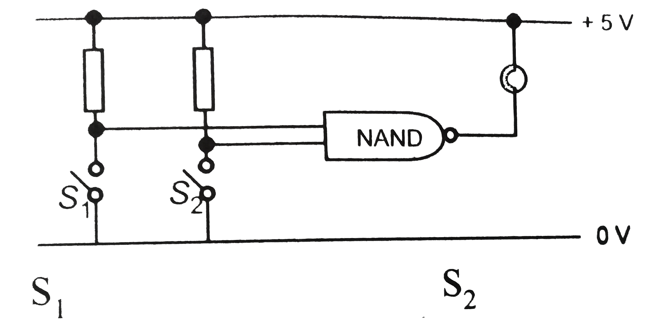
The Diagram Shows A Logic Network Br Img Src Https D10lpgp6

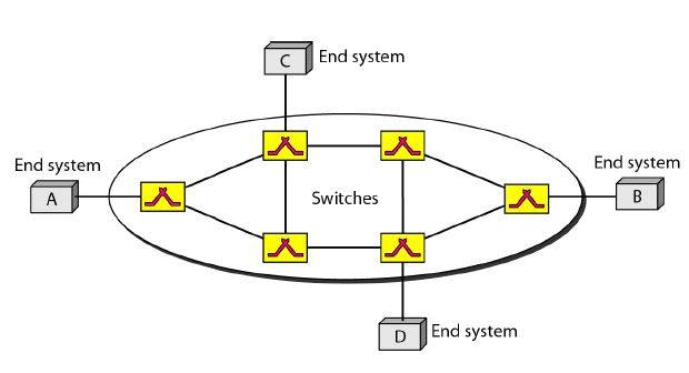
Network Topologies Explained With Examples

15 Best Network Topology Software Mapping Tools Free Paid

Demystifying Vrealize Automation Network Profiles Vmware Cloud

Ee 7402 How To Make A Wiring Diagram In Visio Schematic Wiring
