Alternator External Regulator Wiring Diagram

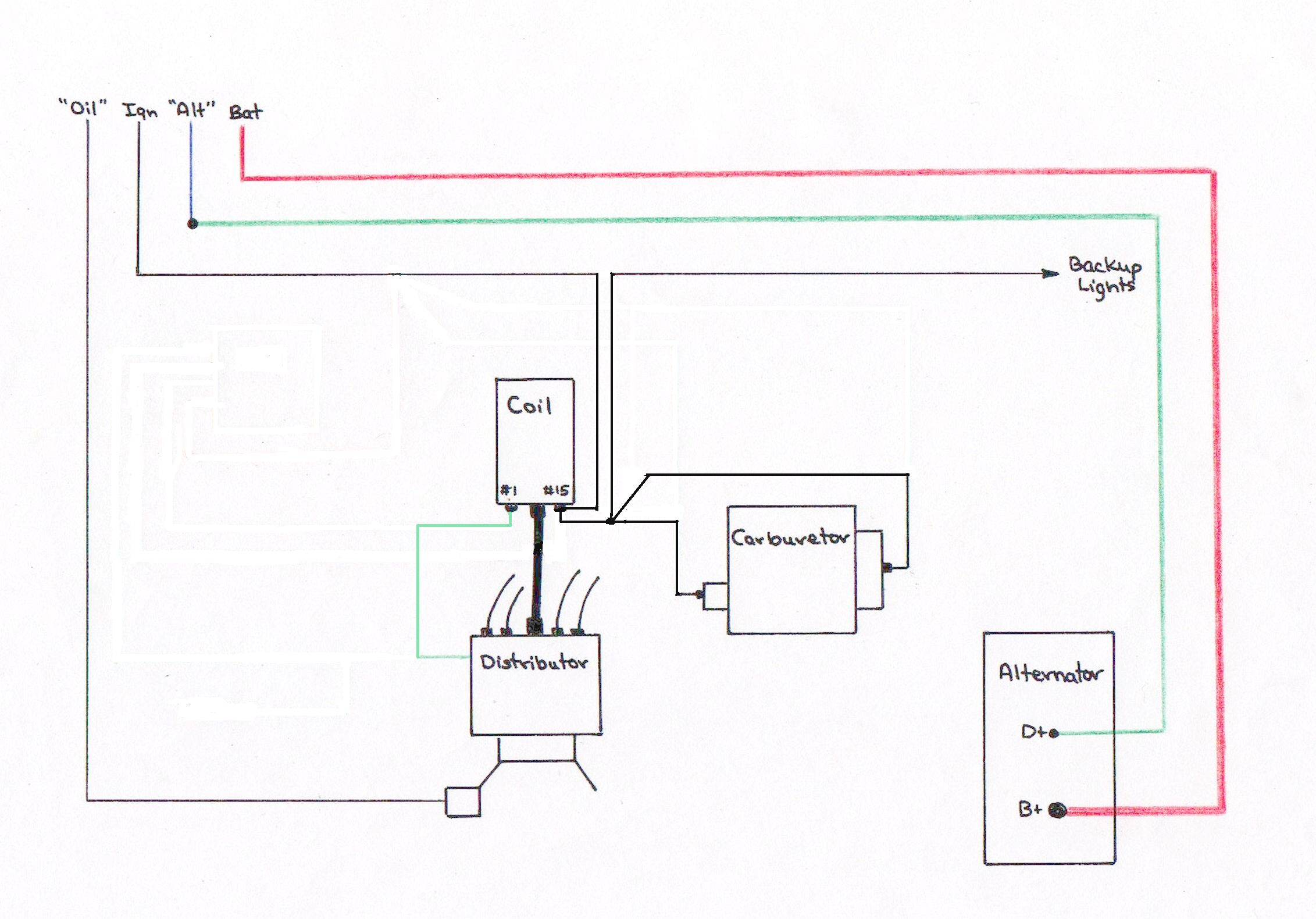
Here Is The Wiring Diagram To Convert Generator To Alternator

Ford Alternator Regulator Wiring Diagram Diagram Base Website

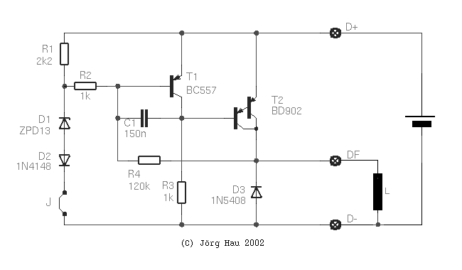
How To Make A Reliable Motorcycle Voltage Regulator 11 Steps
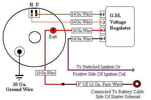
How to wire an external voltage regulator on a gm vehicle.
Alternator external regulator wiring diagram. 800 x 600 px source. Wiring up your gm 3 wire alternator and upgrading from externaly to internaly regulated duration. Output voltage depends on which zener diode you use. Wiring instructions for the early gm delco remy external regulated alternator.
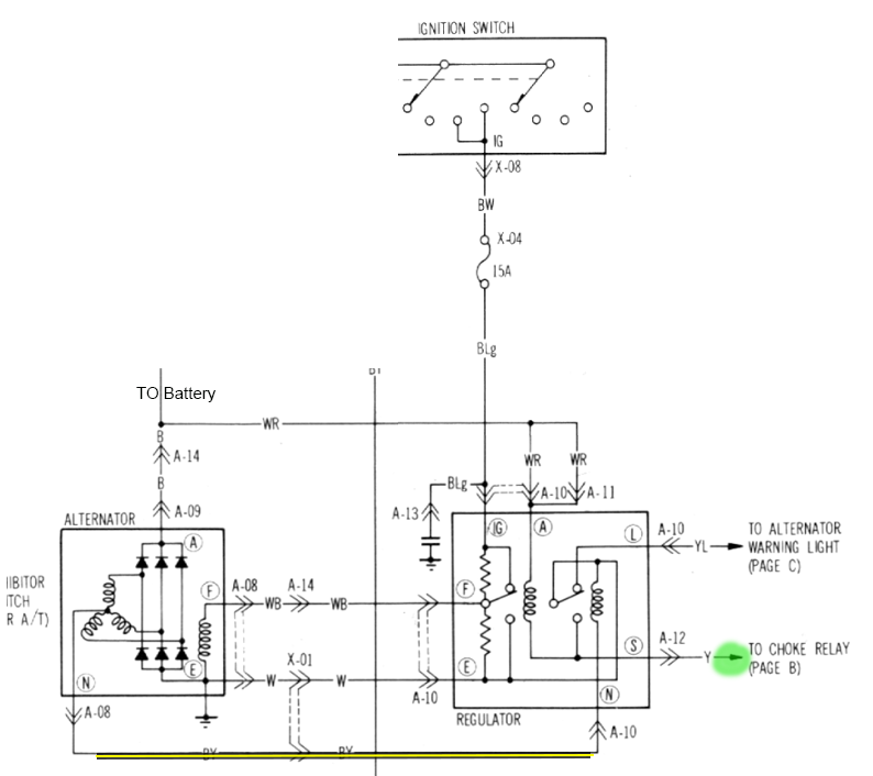
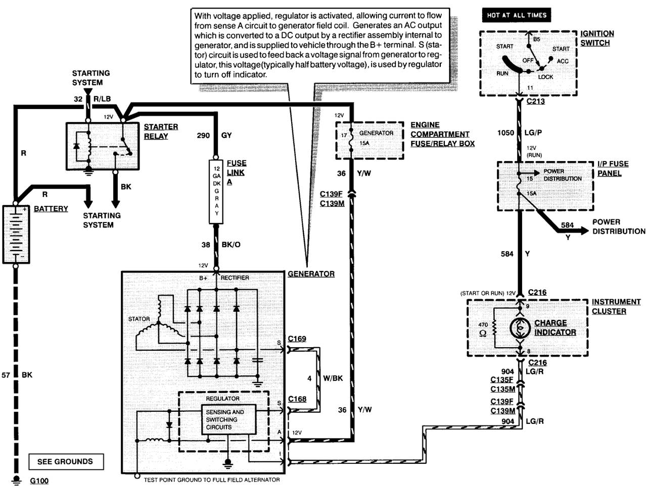
It is very useful if you would like to know the fused power voltage regulator ignition warning and others. Position the alternate regulator on the side of the driver shock tower which is next to the relays. It consists the back view of a standard ford alternator with and without warning light. Too much voltage and your fuses blow if you dont have a regulator.
Leece neville external voltage regulator wiring diagram. This is a basic ford alternator wiring schematic with external regulator. Voltage regulator wiring diagram throughout cristinalattaro size. Most new alternators have internal voltage regulators meaning wiring is not necessary but if you have an external regulator then you need to hook it up to the alternator and ignition system.
Pin on auto diagram how to wire a gm external regulated 10dn alternator alternator wiring with and without the dash warning light dodge chrysler jeep external voltage. How to make an external voltage regulator for any car truck vehicle or boat alternator. The opposite end of one wire goes to the ignition warning lights another is a permanent live low ampere wire that goes to the battery and the third is a low voltage wire that goes to the fuse box. 32 volt a circuit 375 volt set point.
The voltage from your alternator increases and decreases according to the speed the alternator rotates. You find they have plastic plugs on the end and are different sizes so you cant get the wiring wrong. Free ford f150 repair manual online pdf download ford. Below are some of the top drawings we receive from numerous sources we wish these images will certainly serve to you and with any luck very relevant to just what you desire about the ford external voltage regulator wiring diagram is.
Use a 12 or 13 v zener for charging 1 12v lead. Locate three thin wires near the denso alternator. The early gm alternator is the 10dn series alternator and was used on gm vehicles from about 1963 1970. Step 1 install the wires to the alternate regulator.
F64d Wiring Diagram Alternator With Built In Regulator Wiring

80 Gm Alternator Wiring Diagram Diagram Base Website Wiring

Ford Alternator Regulator Wiring Diagram Diagram Base Website
Joergs Motorcycle Pages Voltage Regulator
27e097 Alternator External Regulator Wiring Diagram Wiring Resources

Alternator Wiring Car Electrical Rollaclub Com
Bob S Studebaker Resource And Information Portal 1970 Delco 10dn

Kx 5848 3g Alternator Wiring Mustang Download Diagram

4020 12 Volt Alternator Wiring Diagram Schematic Diagram Base
