Am Receiver Block Diagram Pdf

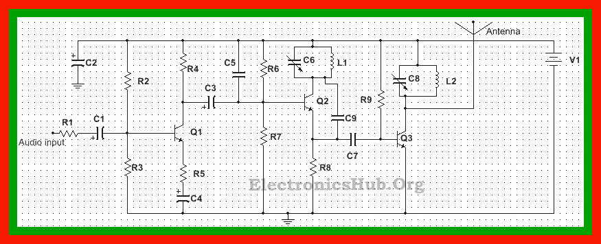
Two Transistor Am Radio Receiver Circuit
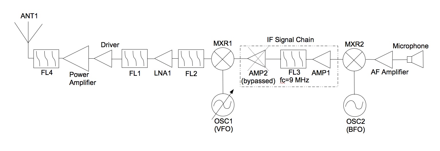
Get Serious With Amateur Radio Design Build A Single Sideband
Dvb S Tuner Block Diagram Auto Electrical Wiring Diagram
Learn everything about am receiver.

Am receiver block diagram pdf. The input signal gets sampled into x1 then comes the block for the removal of a dc component to obtain signal x2. Block diagrams of fm. Fm receiver block diagram. Receiver tutorial circuits am.
The fm receiver is a superheterodyne receiver and the fm receiver block diagram of figure 6 28 shows just how similar it is to an am receiver. The block diagram of the am receiver is depicted in fig. Even many broadcast radios will have am and fm but professional radios used for monitoring and two way radio communications may require a larger variety in some instances. Block diagram of an am receiver.
Totally different methods of demodulation. Generally much higher operating frequencies in fm. The rf amplifier selects one of the many signals on the. Receivers block diagram electronics circuit and tutorials hobby science projects most of these blocks are discussed individually and in more detail on other pages.
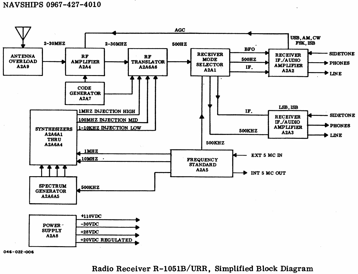
Front end amplifier and tuning block. Block diagram of a basic superheterodyne radio receiver the way in which the receiver works can be seen by following the signal as is passes through the receiver. A superheterodyne receiver usually consists of an antenna rf amplifier mixer local oscillator if amplifier detector af amplifier and a speaker. The input signal for the receiver comes from an antenna but may also come from a suitable amplitude modulated function generator.
See filters mixers frequency changers am modulation and amplifiers. The basic differences are as follows. Signals enter the front end circuitry from the antenna. The superheterodyne receiver block diagram only shows one demodulator but in reality many radio rf designs may have one or more demodulators dependent upon the type of signals being receiver.
The working of a superheterodyne receiver is explained with the help of the block diagram given below in fig along with the waveforms at the output of each block.
2 Km Fm Transmitter Circuit Diagram Working And Applications
Brats Advanced Amateur Radio Tuition Course
Brats Flc Transmitters And Receivers

Block Diagram Of Radio

Heterodyne Wikipedia
Tuned Radio Frequency Receiver Ece4uplp
Amplifiers

Am Radio Circuit Page 3 Rf Circuits Next Gr

Simple Am Receiver Circuit Diagram Receiver Fm Transmitters
