Analog Output Wiring Diagram

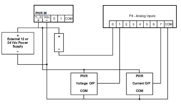
Plc Wiring Diagram Download Scientific Diagram
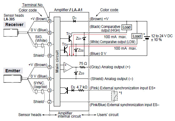
Led Collimated Beam Sensor La 300 I O Circuit And Wiring Diagrams
Analog Input Wiring Diagram Diagram Base Website Wiring Diagram
The device you connect to your analog output is what decides which type of analog signal you should be using.

Analog output wiring diagram. The arduino does not have a built in digital to analog converter dac but it can pulse width modulate pwm a digital signal to achieve some of the functions of an analog output. Controllogix analog io modules catalog numbers 1756 if16 1756 if 6cis 1756 if6i 1756 if8 1756 ir6i. System design for control of electrical noise gmc rm001 in depth information on grounding and wiring allen bradley programmable controllers. This is important to have analog deviced to have the same potential as power supply.
8 pin female terminal block insert module into controller follow the instructions to insert and secure the plug in module to the controller. Pin is the pin number used for the pwm output. Plc analog signals wiring techniques the below figure has the same circuit breaker panel but now it is feeding a dc power supply. Micro800 non isolated unipolar analog output plug in module 5 publication 2080 wd004a en p september 2010 wire the module follow the pinout diagram to wire your plug in module.
The function used to output a pwm signal is analogwritepin value. For this you will only need 2 wires. Ao or analog output is the type of plc output which used to control analog devices. The power supply could be in its own cabinet or it could be in the marshalling panel.
Updated diagram labels for wiring the 1756 if6i module. Again the voltage analog output is the easiest one to wire. Non isolated analog output modules 1756 of4 and 1756 of8. Ao sends a command to the device in the form of electrical current 4 20 ma or electrical voltage.
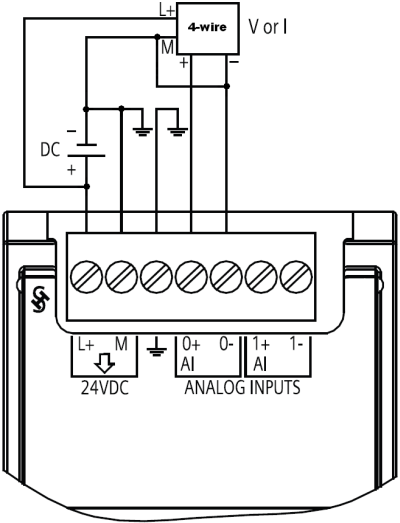
How will do wiring of analog input analog output because there are given 4 wire in analog module in sm322 i want to do wiring 0to10v plz give suggestion if anyone know about it split from 6es7 314 6eh04 0ab0v33 internal aiao module wiring. Dac digital to analog converter inside plc will convert a digital value 12 bit or 16 bit word data resulted from plc calculation to current or voltage and send it to a controlled device through the ao. You connect analog output with two wires ao and mana and also you should connect power supply to module. A description on how to install 4 channel analog io modules slc 500 4 channel analog io modules installation instructions 1746 in008 information on reducing electrical noise.
Electric arduino digital to analog converter top circuits page next gr rr esde lattice. Voltage analog output wiring. Arduino color mixer project hub bb. Value is a number proportional to the duty cycle of the signal.
Arduino er example self adjust analogread to read analog ip from photoresistor and set led matrix accordingly httparduino blogspot int photorespin photoresval.

Wireless Scada I O Expansion Modules
Https Www Emerson Com Documents Automation Manual Digital Futronic Manual Eim En 84502 Pdf
How Do You Connect A Sensor To The Analog Signal Modules Of

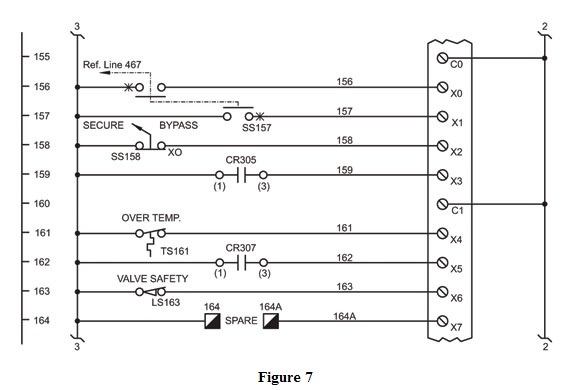
Dcs Loop Wiring Diagram Diagram Base Website Wiring Diagram

Input Isolation For 3 Wire Analog Outputs Precision Hub
Techtalk Scadapack Field Wiring Xybenertics

Specifications Lt Series Products Pro Face

Analog Output
