Analog Wiring Diagram

Plc Input Wiring Diagram
Chapter 2 Page 3 Telecommunications Handbook For Transportation
Voltagetocurrentconverters Addaconvertercircuit Circuit 1
Before reading a wiring diagram learn the different symbols.

Analog wiring diagram. Before you start wiring any plc analog module i highly recommend that you not only read the manual but also know what type of signal youre dealing with. This is a direct. The following wiring diagram shows that how to connect a poe ip ptz camera to the nvr and joystick ptz controller. A wiring diagram is a type of schematic which makes use of abstract pictorial symbols to show all the interconnections of parts in a system.
When wiring optional 240 vac power supply rs 485 relay module or additional analog output module see the appropriate user guide. In this tutorial i will cover wiring of the two most basic analog input signals. Wiring diagram for isolated loop power supplies. Ch1 ch1 ch2 ch2 see figure 1 on the left.
Sample the sample block function is to sample the input analog signal at a specific time interval. Connect the analog output cables to terminals. Download the if6i wiring diagram controllogix analog i o modules rockwell automation controllogix analog i o modules catalog numbers if16 if 6cis if6i if8 ir6i it6i it6i2 of4 of6ci. 2 wire analog transmitters require a loop power supply to power the loop.
Connect the rs 232 user port cables to terminals rxd gnd and txd. Wiring diagram for mulitple loops using a single source power supply. See an overview of the analog input and output modules chapter 1 installation and wiring guidelines chapter 2 input module addressing configuration and status information chapter 3 output module addressing configuration and status information chapter 4. In this wiring connection no need to power up the camera with extra dc supply source as single cat5 or cat6e cable can be used to provide the power to the cameras and transmit the video signals from camera to the nvr as it is an ip poe power over ethernet system.
System using the 1769 analog io modules. Dometic wiring diagrams dometic analog thermostat wiring dometic dometic products campersparadise whats wiring diagram. Wiring of analog inputs. So ideas if you like to get these amazing shots about if6i wiring diagram click save icon to download these shots for your personal pc.
How to read wiring diagrams. Repair faulty wires by learning to read a wiring diagram with tips. Wiring a plc analog input is a bit different depending on the type of signal. The following diagrams describe how this is done with separate power supplies for each loop or a single power supply for all loops.
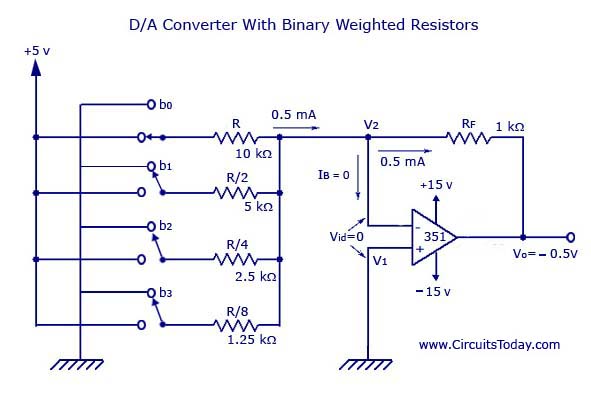
The conversion from analog signal to a digital signal in an analog to digital converter is explained below using the block diagram given above. Part of the series. The power supply could be in its own cabinet or it could be in the marshalling panel.

Hdmi To Vga Wiring Diagram Giant Poli Seblock De

Spitfire Help Desk Wiring Diagram For Analog Dialogic Cards
Controller Mc100 3 Connectors Racom

What Is The Wiring Diagram For The Hmiscu Analog Inputs And
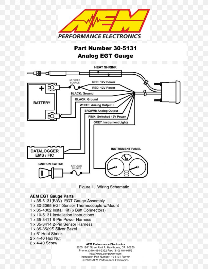
Wiring Diagram Product Manuals Air Fuel Ratio Meter Gauge Png

Led Collimated Beam Sensor La 300 I O Circuit And Wiring Diagrams

Current Loop Connection Divize Industrial Automation

Derive How Do I Wire An Analog Input To My Device
Pressure Sensor Arduino Analog Signal Wiring Diagram Png
