And Gate Wiring Diagram

Logic Circuits

Logic Gate Diagram Template Circuits And Logic Diagram
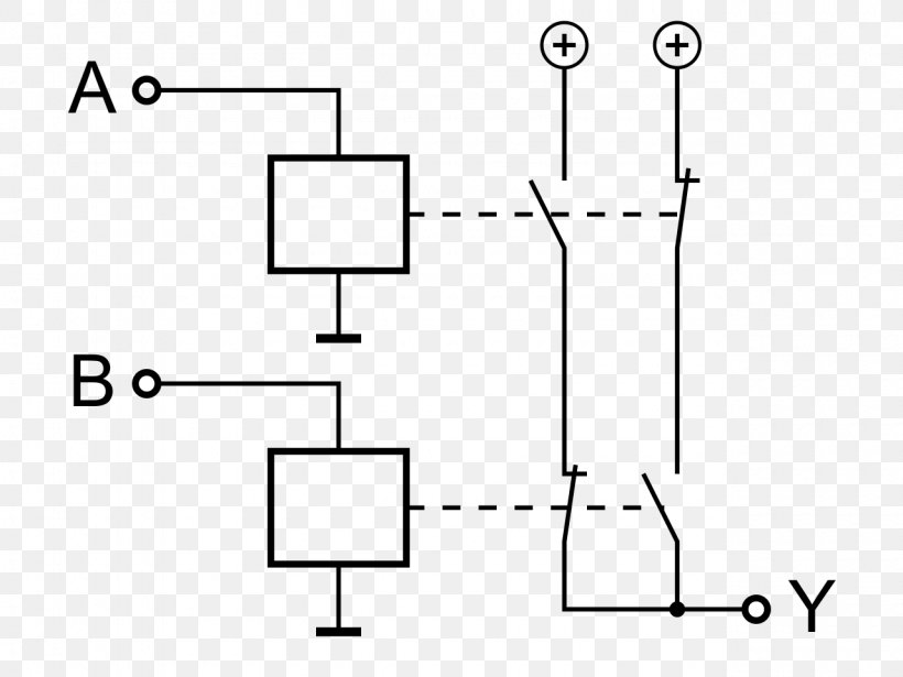
Wiring Diagram Logic Gate Xor Gate Relay Png 1280x960px Diagram
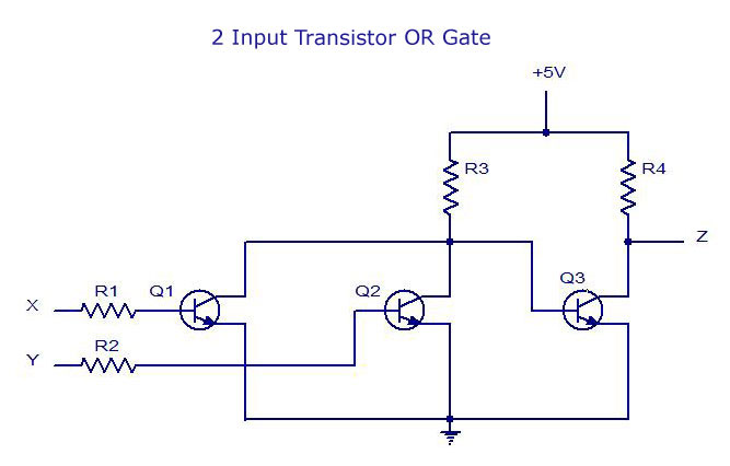
As you can see as long as any one of the inputs is 1 the output will be 1 and only if all inputs are 0 will the result be 0.

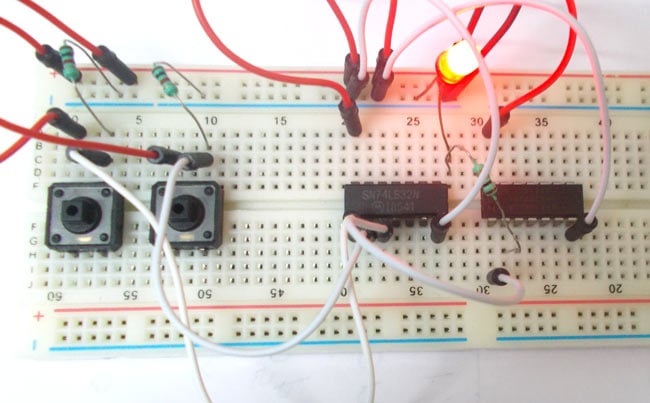
And gate wiring diagram. Led dip umcb 01 ctrl wiring umcb 01 ctrl. An and gate is a logic circuit that only turns on an output when all the inputs are high or a logic state of 1. If the inputs are of x and y then the output can be represented as zxy. So with two buttons we can realize the truth table of and gate.
Lets look at the or gates truth diagram. Wiring diagram 6103 universal gate board function. The or gate produces an output of logic 1 state even if any of its inputs is in logic 1 state and also produces an output of logic 0 state if any of its inputs is in logic 0 state. A list of electrical symbols and descriptions can be found on the electrical symbol page.
The symbol for or operation is aaaaaa. So when the button is pressed the corresponding pin of gate goes high. And then the inputs are connected to power through a button. Wiring diagram 5633 dr.
If any inputs are off or at a logic state of 0 the output is off. For and gate ic number in ttl is 7408. Wiring diagram 6103 catalog cut wiring diagrams 6001sl. 7408 is quad 2 input ic where four gates are present together.
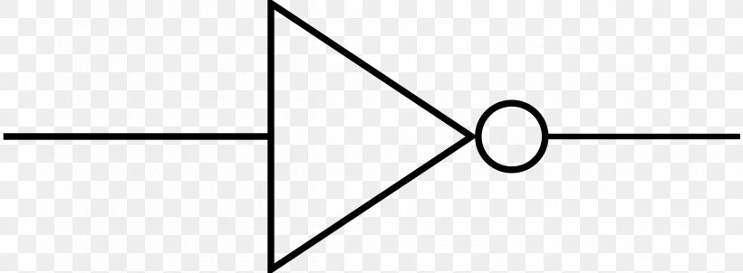
Here pln 1 2 are the inputs of the first gate whose respective output is 3. In this circuit we are going to pull down both input of a gate to ground through a 1kw resistor. The circuit symbol is that arrowhead kind of shape and inputs and outputs are marked the same way as the and gate. In this project we will show how to build an and gate circuit with diodes.
Wiring diagram 5631 dr. Let us have a look on the internal diagram of 7408.

Lessons In Electric Circuits Volume Iv Digital Chapter 6

Logic Not Gate Tutorial With Logic Not Gate Truth Table

Wiring Diagram Example For A Dc Motor Automatic Gate Johor
Digital Electronics Logic Gates Basics Tutorial Circuit Symbols
1
Power Inverters Logic Gate Electronics Wiring Diagram Png
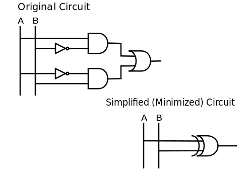
Logic Optimization Wikipedia
Nor Gate Circuit Diagram Working Explanation

Xor Gate Circuit Con Imagenes
