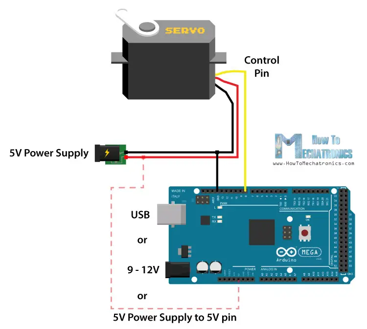
Arduino Servo Motor Wiring Diagram
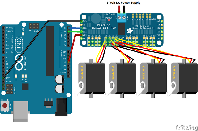
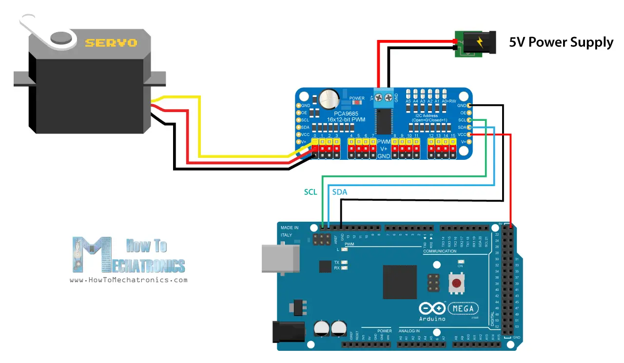
Adafruit Pca9685 Pwm Servo Driver Setup Arduino Library Use Shown

Nx 3151 Servo Motor Control Schematic Pyroelectro News Projects

Controlling Servo Angle Using Joystick In Arduino Ide Stempedia
Watch this tektips video to learn the easy process of wiring an arduino to a clearpath integrated servo motor.
Arduino servo motor wiring diagram. Like other rc servos the motor rotates from 0 to 180 degree based on the duty cycle of the pwm wave supplied to its signal pin. 1 x towerpro sg90 servo motor. Find out more below. 3 x jumper wires.
A better look at the circuit board dc motor and potentiometer. Servo yellow wire pwm9 pin arduino. The best thing about a servo motor is that it can be connected directly to an arduino. Thanks to arduino servo library controlling servo motor is a piece of cake.
The best thing about a servo motor is that it can be connected directly to an arduino. The mg996r is a metal gear servo motor with a maximum stall torque of 11 kgcm. Find out more below. Servo motors that dont produce high torque typically contain plastic gears.
Servo brown wire ground pin arduino. It shows the components of the circuit as streamlined forms and the power and signal connections in between the devices. Variety of servo motor wiring diagram. Some of arduino pins can be programmed to generate pwm signal.
Connect to the motor to the arduino as shown in the table below. Connect to the motor to the arduino as shown in the table below. Servo motor wiring diagram adafruit comes with one horn only as shown to control with an arduino we suggest connecting the white control wire to pin 9 or 10 and using the servo library included. Microcontrollers are an excellent way of controlling and.
We can control the servo motor by connecting the servo motors signal pin to an arduinos pin and programming to generate pwm on the arduinos pin. Servo motor control with an arduino. Arduino servo motor. Following are the steps to connect a servo motor to the arduino.
Watch this tektips video to learn the easy process of wiring an arduino to a clearpath integrated servo motor. However larger servos might draw more current which can reset the arduino. Arduino to servo motor wiring diagram. The 48 to 6v positivered wire to servo motor run servos white control wire to pin d5 run separate 12v to vin pin on nano and the same 12v sources ground to the grn pin next to vin shout out and thanks a ton to zoomkat for the first code for the momentary switch.
I have learned a ton. Servo motors are often driven using the pwm outputs available on up to your pi is with the adafruit pi cobbler as seen in the wiring diagram. Servo wiring diagram arduino. A wiring diagram is a simplified conventional pictorial depiction of an electric circuit.
Servo red wire 5v pin arduino.

A3952s Dc Servo Motor Controller Circuit Diagram Circuit Diagram

Controlling Of Servo Motor With Arduino And Mpu6050 Arduino

Arduino Servo Motor Control Circuit Using Joystick And 9v Battery

Controlling Servo Motors With Arduino Tutorial Australia
Simple Servo Motor Circuit Diagram

Servo Motor Interfacing With Arduino Arduino Servo Control
How Servo Motor Works How To Control Servos Using Arduino
How Servo Motor Works How To Control Servos Using Arduino
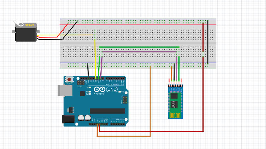
Bluetooth Controlled Servo Arduino Project Hub
