Basic 4 Stroke Engine Diagram
Four Stroke Engine High Resolution Stock Photography And Images
4 Stroke Engine Cycle Diagram Agricultural Engineering

State Machine Of A 4 Stroke Engine Cycle Download Scientific
This video is about the basic components of an engine.

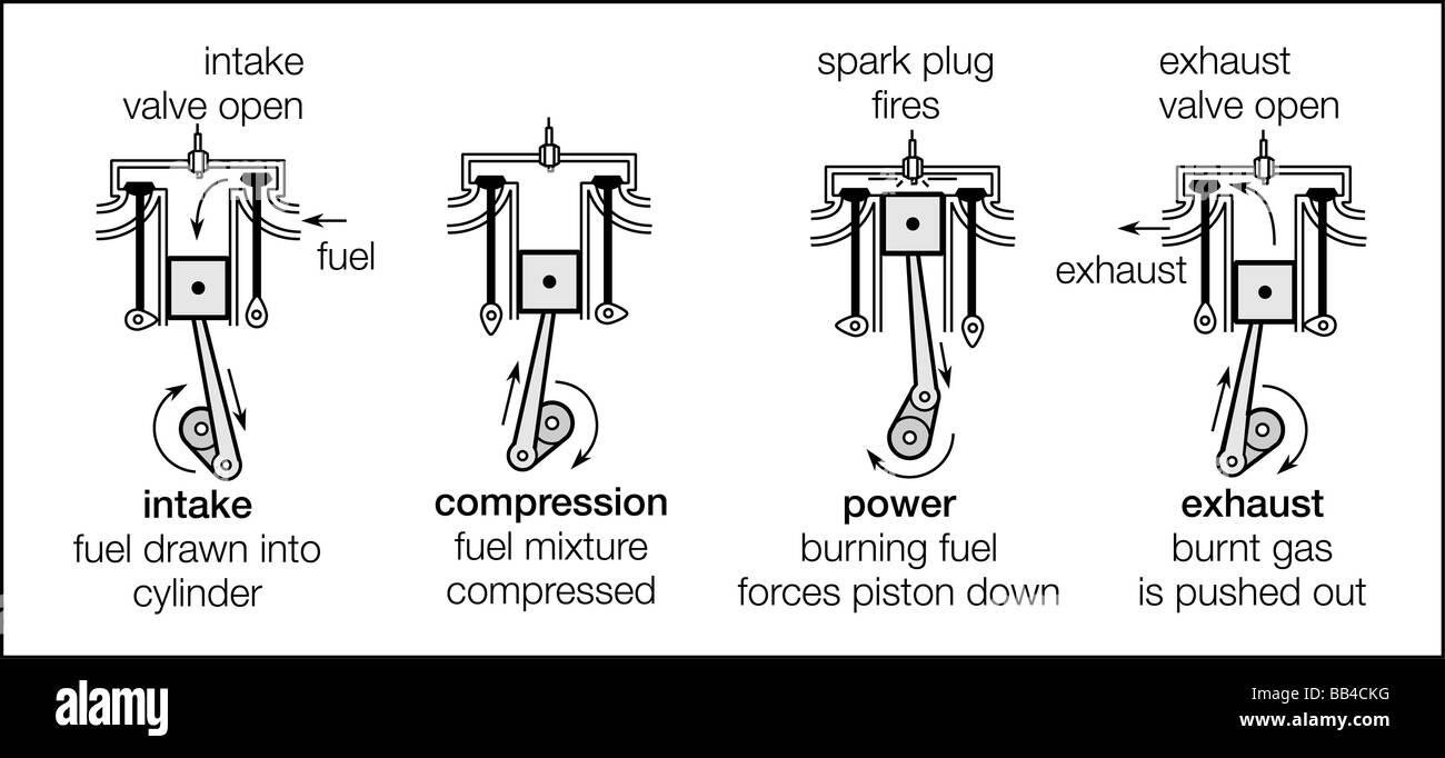
Basic 4 stroke engine diagram. The four stroke engine in diagram of a 4 stroke engine image size 361 x 425 px and to view image details please click the image. The four stroke engine was first demonstrated by nikolaus otto in 1876 1 hence it is also known as the otto cycle. Their engine operation is named 4 stroke because the engine does a cycle of tasks which is separated in 4 stages. A four stroke also four cycle engine is an internal combustion ic engine in which the piston completes four separate strokes while turning the crankshaft.
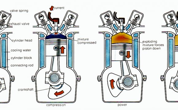
As the 2 stroke engine animation below shows a two stroke engine in its purest form is extremely simple in construction and operation as it only has three primary moving parts the piston connecting rod and crankshaft. Learn about the basic components and the working of an four stroke automobile diesel engine. A four stroke engine has four main strokes to its cycle. The four stroke engine is probably the most common engine type nowadays.
Here is a picture gallery about diagram of a 4 stroke engine complete with the description of the image please find the image you need. How diesel engines work part 3 valve timing diagram duration. However the two stroke cycle can be difficult for some to visualize at first because certain phases of the cycle occur. The four separate strokes are termed.
After this is complete the camshaft rotates to the low spot on the lobe. Remember to check for other relevant information in the columns and article tables. The first stroke called the intake stroke the crankshaft pulls down the piston by rotating. A stroke refers to the full travel of the piston along the cylinder in either direction.
Also known as induction or suctionthis stroke of the piston begins at top dead center tdc and. The technically correct term is actually four stroke cycle. Technical documents documentos tecnicos. It powers almost all cars and trucks.
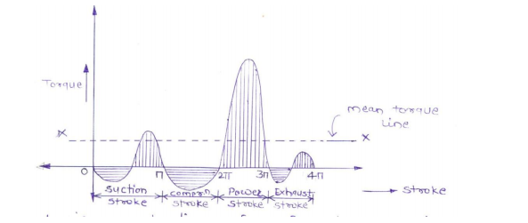
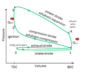
If you enjoyed the information and article you just read be sure to check out our newly released book with even more exciting photos and information. Valve timing diagram for 4 stroke engine petrol and diesel as we all know in 4 stroke engine the cycle completes in 4 strokes that are suction compression expansion and exhaust the relation between the valves inlet and outlet and piston movement from tdc to bdc is represented by the graph known as valve timing diagram. Intake stroke the piston moves downwards and the intake valves opens up to fill the chamber with the mixture fuel air while the exhaust valves are closed. Subscribe for more update like comment and share this video with your friends.

Internal Combustion Engine Wikipedia

The Four Stroke Engine Cycle 1 Download Scientific Diagram

What Is Diesel Cycle Processes With P V And T S Diagram
Explain Single Cylinder 4 Stroke I C Engine Using Turning Moment

The Marine Diesel Prime Mover The Two Stroke Plant

Four Stroke Engine With P V Diagram Hd Youtube
Four Stroke Engine Energy Education

Exhaust Stroke Stock Illustration Illustration Of Auto 49912714

4 Stroke Gas Engine Parts
