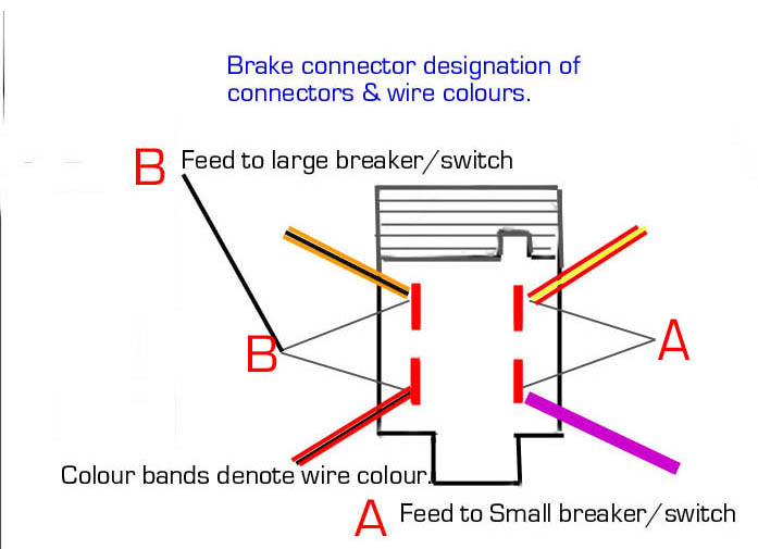
Basic Brake Light Switch Wiring Diagram
Bert Rowe S Mercedes Benz A Class Info Brake Servo Foot Brake

Solved Electrical Diagrams For Brake Lights And Turn Fixya

Basic Wiring Diagram For Bikes Trikes
Master auto mechanic shows you the method that brings success to do it yourself electrical auto repair.

Basic brake light switch wiring diagram. Assortment of third brake light wiring diagram. Multiple light wiring diagram. Now is necesary turn signal. The source is at sw1 and 2 wire cable runs from there to the fixtures.
It shows the parts of the circuit as simplified shapes as well as the power and signal connections in between the gadgets. A wiring diagram is a streamlined conventional photographic depiction of an electric circuit. As promised a short video and wiring schematic to wire stop turn and tail lights to dual filament bulbs 1157 using relays. This color coding makes it easier for the layman to quickly repair most automobile wiring issues.
Simple wiring help brake lights running lights turn signal dear chuck. Automotive wiring has been standardized over the decades and most cars will have color coded wiring for lighting radio ignition and secondary systems. I have included the schematic for the headlight relay also. The electricity flows from the hot wire black through the 2 way switch shown in off position and then to the light and returns through the neutral wire white.
The hot and neutral terminals on each fixture are spliced with a pigtail to the circuit wires which then continue on to the next light. I have made many electrical diagrams to put in my vehicle land rover serie i 1956 it has the genuine red lamps it were made only with brake and tail lamps. You can learn to understand the wiring diagrams by. By wiring a 2 way switch the circuit below shows the basic concept of electricity flow to the load.
Once the switch has power you need to connect the output wire from the switch to the rest of the brake light wiring harness. Visit howstuffworks to check out this brake light wiring diagram. Lets assume the load you are controlling is a light. This diagram illustrates wiring for one switch to control 2 or more lights.
A wiring diagram for your specific vehicle will show you which wire in the bundle to splice. Learn how to use an automotive wiring diagram to fix car electrical problems.
Https Encrypted Tbn0 Gstatic Com Images Q Tbn 3aand9gctpbw Cqe4ztw J Ecimzs1h2th1g1x8hto Ahgvms9hdcjqwvx Usqp Cau
Test Light Wiring Diagram Wiring Diagram
Simplified Motorcycle Wiring Harness Motorcyclezombies Com
2
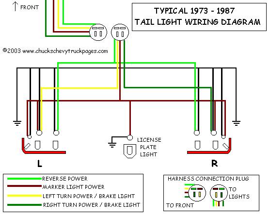
Headlight And Tail Light Wiring Schematic Diagram Typical 1973

Hhr Third Brake Light Problems Chevy Hhr Network
Https Www Painlessperformance Com Manuals 10308 Pdf

Simple Brake Light Switch Instructables

1999 Polaris Ranger 500 Wiring Diagram Diagram Base Website Wiring
