Basic Hydraulic Circuit Diagram Pdf
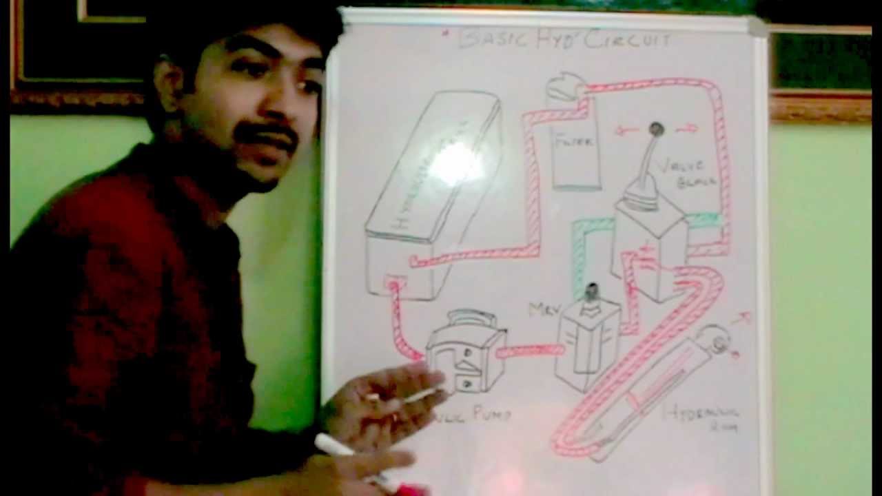
Basic Hydraulic Circuit Must Watch Youtube

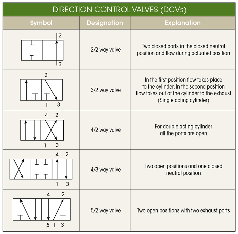
What S The Difference Between Hydraulic Circuit Symbols Machine
How Hydraulic Circuit Works Part 2 Youtube
Hydraulic circuit design and analysis a hydraulic circuit is a group of components such as pumps actuators and control valves so arranged that they will perform a useful task.
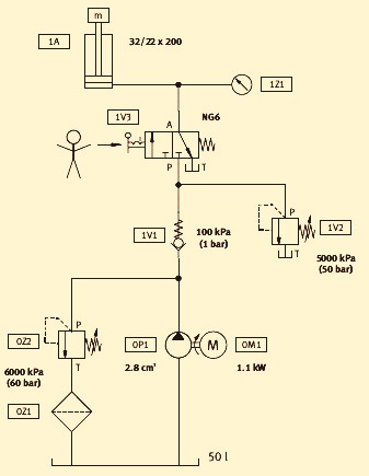
Basic hydraulic circuit diagram pdf. Local area number 1. An alternative circuit diagram is shown in figure 512. 122 purpose 1221 the purpose of this standard is to provide a system of fluid power graphic symbols for industrial and educational purposes. A hydraulic motor is a mechanical hydraulic actuator that converts hydraulic energy or hydraulic pressure into torque and angular displacement rotation.
For example metering circuits offer precise control of actuator speed without a lot of complicated electronics decompression circuits reduce pressure surges within a hydraulic system by controlling the release of stored fluid energy and pump unloading and regenerative circuits make a system more energy. 1216 this standard provides basic symbols which differentiate between hydraulic and pneumatic fluid power media. Interaction of components the animations show the sequences in a basic hydraulic circuit in simplified form the actuation and spring return of the final control element 42 way valve the advance and return of the drive component double acting cylinder and the opening and closing of the. Safety of operation 2.
Basics of hydraulic circuits. Circular large circle pump motor small circle measuring devices semi circle rotary actuator square one square pressure control. Hydraulic systems 9 toro university technical training understanding the basic hydraulic systems and components can be of great value when troubleshooting and testing hydraulic equipment. Fluid power systems theory and practiceppt.
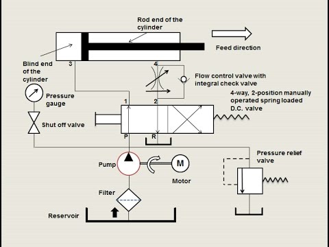
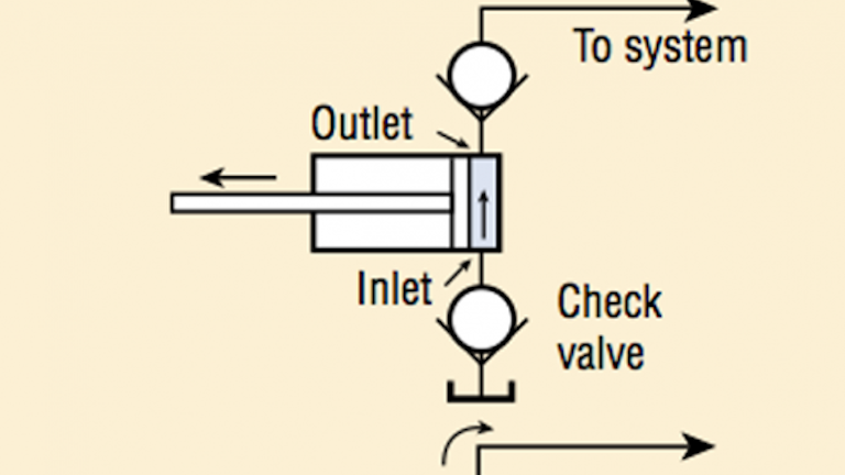
Hydraulic circuits tutorialpdf free download as pdf file pdf text file txt. The upper illustration would be a circuit used to raise a cutting unit with a hydraulic cylinder. With the basic function understood a detailed study of the diagram can be accomplished using a step by step analysis of each numbered local area in the diagram. Hydraulic systems are often used in press work or other applications where the work piece must be held in place.
Types of hydraulic motors and their symbol used in hydraulic circuit diagram. Hydraulic schematic symbols airline hydraulics main page basic symbols lines continuous line flow line dashed line pilot drain envelope long and short dashes around two or more component symbols. In part c a hydraulic crane is selected and the hydraulic components used in the hydraulic cranes were identified the hydraulic circuit of the crane and the mode of actuation of the different. Many circuits are used frequently in fluid power systems to perform useful functions.
Symbol for an open reservoir with a strainer.
Basic Hydraulic Circuit

Hydraulic Schematics Pdf Auto Electrical Wiring Diagram
What S The Difference Between Hydraulic Circuit Symbols Machine

Basic Hydraulic Schematics Youtube
Engineering Essentials Fundamentals Of Hydraulic Pumps
Basic Simple Hydraulic System Diagram

Hydraulic Circuit Diagram For A System That Clamps Then Drills

Hydraulic System For Beginners Com Imagens Engenharia Mecanica
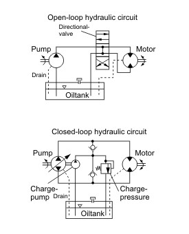
Hydraulic Circuits Open Vs Closed Hydra Tech
