Block Diagram Notation

Electronics Club Circuit Symbols
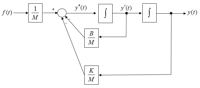
Differential Equation State Space Sharetechnote

Functional Flow Block Diagram Wikipedia
This sample was created in conceptdraw diagram diagramming and vector drawing software using the uml use case diagram library of the rapid uml solution from the software development area of conceptdraw solution park.
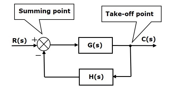
Block diagram notation. In mathematics a block matrix or a partitioned matrix is a matrix that is interpreted as having been broken into sections called blocks or submatrices. To conclude block diagram notation offers a powerful way of describing complex dyanamic systems. Use case diagram taxi service uml. Let us consider the block diagram of a closed loop control system as shown in the following figure to identify these elements.
Simulink modeling 4 cruise control. Basic elements of block diagram. This is the final diagram for the simultaneous equation. Simulink modeling 3 suspension.
The graphic nature of the representation often reveals system structure that might not be apparent when looking at traditional equation form descriptions of the system. A block diagram is a diagram of a system in which the principal parts or functions are represented by blocks connected by lines that show the relationships of the blocks. Block diagrams are typically used for higher level less detailed descriptions that are intended to. The basic elements of a block diagram are a block the summing point and the take off point.
Intuitively a matrix interpreted as a block matrix can be visualized as the original matrix with a collection of horizontal and vertical lines which break it up or partition it into a collection of smaller matrices. Connecting the common variables with arrows we will get a combined diagram as shown below. It is used to design new systems or to describe and improve existing ones. They are heavily used in engineering in hardware design electronic design software design and process flow diagrams.
The above block diagram consists of two blocks having transfer functions gs and hs. Block diagram what is a block diagram. A block diagram is a specialized high level flowchart used in engineering.

G Parameters Model A Equivalent Electrical Circuit B Block
Block Diagram Maker Lucidchart

Function Blocks In Programmable Logic Controllers Tutorial 17 June
Control Systems Block Diagrams Tutorialspoint
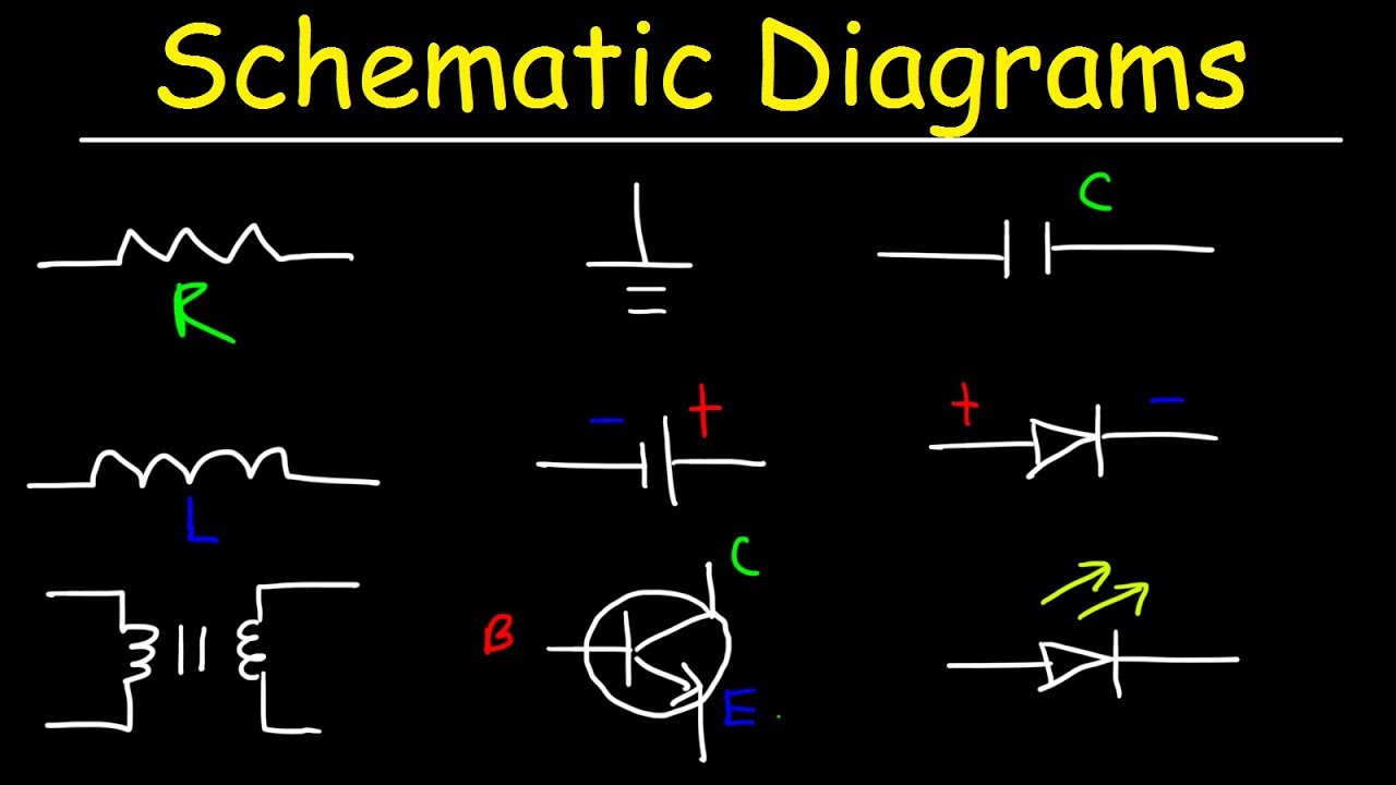
Schematic Diagrams Symbols Electrical Circuits Resistors

Schematic Block Diagram Of The Real Time Implementation Notation

Functional Flow Block Diagram Wikipedia

Circuit Diagram Wikipedia

Oe 8362 Sound System Block Diagram Symbols
