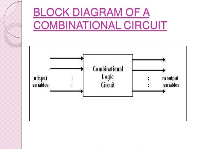
Block Diagram Of Combinational Circuit

Computer Organization Architecture Digital Logic
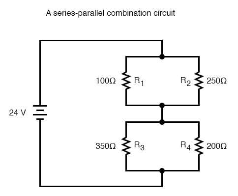
Analysis Techniques For Series Parallel Resistor Circuits Series

Simple Combinational Circuit Using Virtual Block Download
These are most commonly used in various applications especially in the field of digital signal processing to perform the various algorithms.

Block diagram of combinational circuit. It can add two one bit numbers a and b and carry c. This type of circuits uses previous input output clock and a memory element. The logic gates accept signals from the input variables and generate output signals. Full adder is developed to overcome the drawback of half adder circuit.
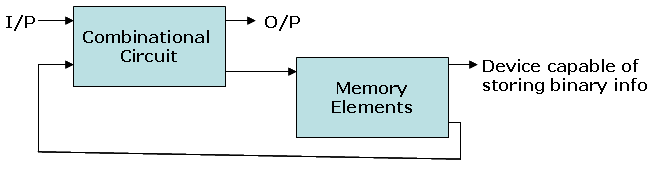
Hence the previous state of input does not have any effect on the present state of the circuit. This process transforms binary information from the given input data to the required output data. Block diagram flip flop. Sequential circuits are essentially combinational circuits with feedback.
Block diagram of a combinational logic circuit. Add a memory element and feedback to a combinational circuit and you get a sequential circuit. Both the inputs and outputs can reach either of the two states. Its design employs one or more inputs and one or more outputs whose states are related to some definite rules that depend on previous states.
A basic binary adder circuit can be made from standard and and ex or gates allowing us to add together two single bit binary numbers a and b. Another common and very useful combinational logic circuit which can be constructed using just a few basic logic gates allowing it to add together two or more binary numbers is the binary adder. Combinational circuit in hindi block diagramtypes of combinational circuit knowledge. A block diagram of a generalised sequential circuit is shown in fig.
Logic 0 low or logic 1 high. Block diagram truth table circuit diagram n bit parallel adder. Block diagram of a sequential logic circuit. A combinational circuit consists of input variables logic gates and output variables.
The addition of these two digits produces an. But sequential circuit has memory so output can vary based on input. A sequential logic circuits is a form of the binary circuit. Block diagram truth table circuit diagram full adder.
Full adder in hindi block diagram truth table implementation designing expression sum and carry. The combinational circuit does not use any memory. The full adder is a three input and two output combinational circuit. A binary multiplier is a combinational logic circuit used in digital systems to perform the multiplication of two binary numbers.
Difference between combinational and sequential circuit prerequisite combinational circuits using decoder introduction of sequential circuits combinational circuits are defined as the time independent circuits which do not depends upon previous inputs to generate any output are termed as combinational circuits. Commercial applications like computers mobiles high speed calculators and some general purpose processors require. In these circuits their output depends not only on the combination of the logic states at its.

7 2 Combinational Logic Circuits Introduction To Digital Systems
Sequential And Combinational Circuits Digital Logic Design

Combinational Circuit World Of Computing

Basic Combinational Circuits Types Examples Video Lesson
Combinational Circuits
Difference Between Combinational And Sequential Circuit Vertical

Block Diagrams Of The Observed Combinational Circuits

Untitled Document

Dld Co Electronic Circuits Logic Gate
