Breaker Schematic
Circuit Breaker Connection
Circuit Breaker Block Diagram

Reyrolle Lmt Breaker Retrofit Bu Ppmv Pg Service Marketing And
Ac device that we use in our homes generally have a limit to handle the current and voltagethese threshold voltage and current are called the device rating and are the measurements given by the manufacturers in the range of which the device will work properly.

Breaker schematic. Click on the circuit breaker to release the switch. The symbol for a thermal fuse used in any electrical circuit diagram. Ill be leaving it just like this for a while. 15amp 20amp 30amp and 50amp as well as a gfci breaker and an isolated ground circuit.
Read further for the explanation of the same. Its funny that this is just about how i used to set my bluesbreaker combo. Some circuit breakers use an explosive charge to throw the switch. Understanding a breaker scheme is important if you plan on designing a substation.
The figure below depicting a circuit breaker scheme will be used to explain various elements of the pcbs design and its control. As shown above in circuit breaker schematic it is really simple and just a bunch of resistors capacitors and other stuff. A bimetallic strip design works on the same principle except that instead of energizing an electromagnet the high current bends a thin strip to move the linkage. I wanted to reduce the amount of gain somewhere in the amp which is the main reason i wanted to look at the schematic but after seeing what a 12ay7 does i have pretty much achieved my aim.
Drawing circuits should be as easy as using google docs start collaborating more effectively with electra cloud electra cloud learn more sign me up drawing circuits should be as easy as using google docs electra cloud learn more sign me up electra cloud is the next generation cloud based electrical schematic software that lets you collaborate more effectively with teams. We will be using this simple diagram to discuss the components involved with the electrical operating sequence of a circuit breaker. The complete schematic diagram of electronic circuit breaker is given in the image below. Electronic circuit breaker circuit diagram working and applications.
When current rises above a certain level it ignites explosive material which drives a piston to open the switch. A thermal fuse is a temperature sensitive switch. This page contains wiring diagrams for a service panel breaker box and circuit breakers including. This diagram illustrates some of the most common circuits found in a typical 200 amp circuit breaker service panel box.
Circuit breaker control schematic explained a typical wiring diagram with dc control for a westinghouse dhp is shown in the figure below. Quite often it is overwhelming to make sense of the entire scheme at a glance.

Vs1 C一12 Series Indoor High Voltage Vacuum Circuit Breaker

Astrol Dc Breaker Block Diagram Pulse Power Measurement Ltd

Typical Circuit Breaker Control Circuit Motor Spring Operated

Closing Control Schematic Of Circuit Breaker Youtube
Https Www Eaton Com Ecm Groups Public Pub Electrical Documents Content Il01209005e Pdf

Arduino Circuit Breaker Arduino Project Hub
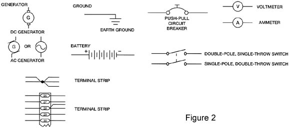
Electrical Systems Simplified Part 2 By Ron Alexander
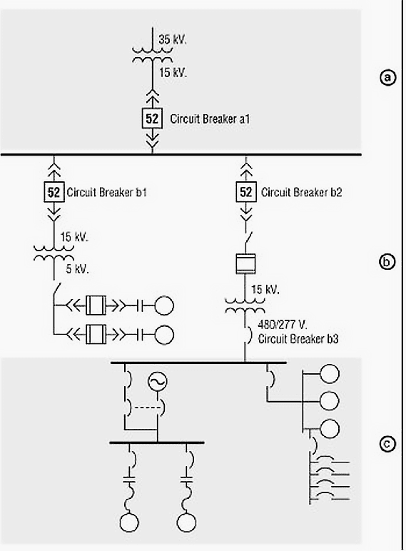
Learn To Interpret Single Line Diagram Sld Eep

Schematic Diagram Of A Circuit Breaker Based Interconnection
