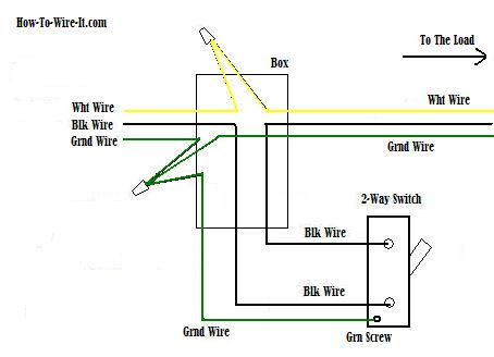
Ceiling Fan Dual Switch Wiring Diagram
A wiring diagram is a streamlined standard pictorial depiction of an electrical circuit.

Ceiling fan dual switch wiring diagram. Collection of 4 wire ceiling fan switch wiring diagram. A wiring diagram is a simplified conventional photographic depiction of an electric circuit. The switch replacement is below. Separate switches for bath fan and light from single switch in a 1960s house duration.
This wiring configuration is not preferred in new construction instead it is recommended that power be routed to the switch box if possible. Sparky channel 24095 views. A single wall switch controls the power to the fan and light together whereas a dual wall switch has two separate switches one for the fan and the other for the light. Does anyone have a wiring diagram for recent hunter ceiling fans including the sell the entire switch housing containing the switch capacitor etc.
A dual wall switch was always used to control the light and fan separately on the older fan. Variety of hampton bay ceiling fan wiring schematic. The ceiling fan that was up before had a remote and the switches on the wall worked 1 switch had to be on in order for the remote to work and the other controlled power to the fan. The wiring instructions for your new hunter fan differ slightly based on the type of wall switch and your fans control system pull chain remote control etc.
3 green hi speed l1. I recently bought a new ceiling fan and light kit to replace one that had been in my sun porch for over 20 years. Wiring for dual wall switch to control ceiling fan and light separately 20 answers greetings. The fan speeds were controlled by pull chain.
It reveals the elements of the circuit as simplified shapes and the power and signal connections between the tools. Switched lines and neutral connect to a 3 wire cable that travels to the lightfan outlet box in the ceilingthe fan control switch usually connects to the black wire and the light kit switch to the red wire of the 3 way cablein this diagram the black wire of the ceiling fan is for the fan and the blue wire. For a hampton bay fan 4 wire capacitor 3 speed switch. Hunter ceiling fan 3 speed capacitor wiring diagram we bought a dual capacitor 3 speed fan switch replaced it wire for i was not able to find a general wiring diagram for these things so im.
It reveals the components of the circuit as simplified forms and also the power and signal connections in between the devices. Line voltage enters the switch outlet box and the line wire connects to each switch.