Combination Motor Starter Wiring Diagram
Http Www Rses Org Assets Serviceapplicationmanual 620 37 Pdf

Motor Protection And Control Abb
2
Allen bradley motor starter wiring diagram fresh fine allen bradley.
Combination motor starter wiring diagram. Interchangeable fuse clips straight through wiring space for a fused control transformer with. Time lapse of schematic diagram drawn into a wire diagram and the wiring of the magnetic motor starter. Combination starter enclosures are turn key control panel solutions that incorporate a magnetic starter contactor thermal overload short circuit protection and a means of disconnect into a single enclosure. A wiring diagram gives the necessary information for actually wiring up a group of control devices or for physically tracing wires when trouble shooting is necessary.
Starting a three phase motor. In north america an induction motor will typically operate at 230v or 460v 3 phase 60 hz and has a control voltage of 115 vac or 24 vdc. Start stop 3 wire control. The design of the fusible disconnect switch combination starter uses a flange operated visible blade switch.
Square d size 1 starter wiring diagram magnetic motor definite. A motor starter is a combination of devices used to start run and stop an ac induction motor based on commands from an operator or a controller. These panels offer short circuit protection in the form of a manual motor starter circuit breaker or fusible disconnect. Original a motor starter is a combination of devices to allow an induction motor to start run and stop according to commands by an operator or a controller.
The wiring diagrams heavy lines. How to wire a motor starter number. Wiring diagrams 55 57 type s ac combination magnetic starters58 59 class 8538 and 8539 58 59 3 phase size 0 5 58 3 phase additions and special features 59. Class 8538 combination starters are available in nema size 06.
Nema freedom starters wiring diagrams reversing starter reversing starter non combination reversing starter combination f r f r f r a1 4 2 if used a2 a1 5 7 3 6 a2 1 ol remote control stations starter elementary diagram l1 l2 l3 ac motor t1 t3 t2 lines contactors f and r are mechanically interlocked ol ol r f f rls f r fls. A line diagram gives the necessary informa tion for easily following the operation of the various. Eaton motor starter wiring diagram. Typically an induction motor will run by a.
G l1 l2 l1 l2. M a1 a2 m.
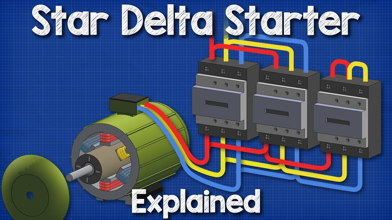
Star Delta Starter

Image Result For Dodge Starter Relay Wiring Diagram Automotive

An 9897 Ge Motor Starter Wiring Diagram Wiring Diagram

Square D Size 0 Ac Combination Motor Starter 30a Model
Motor Control Circuit Diagram Pdf

Dol Starter Direct Online Starter Diagram Working Principle

Dol Starter With Overload Wiring Diagram

Motor Protection And Control Abb

Starter Solenoid The Definitive Guide To Solve All The Solenoid
