Connection Time Delay Relay Wiring Diagram
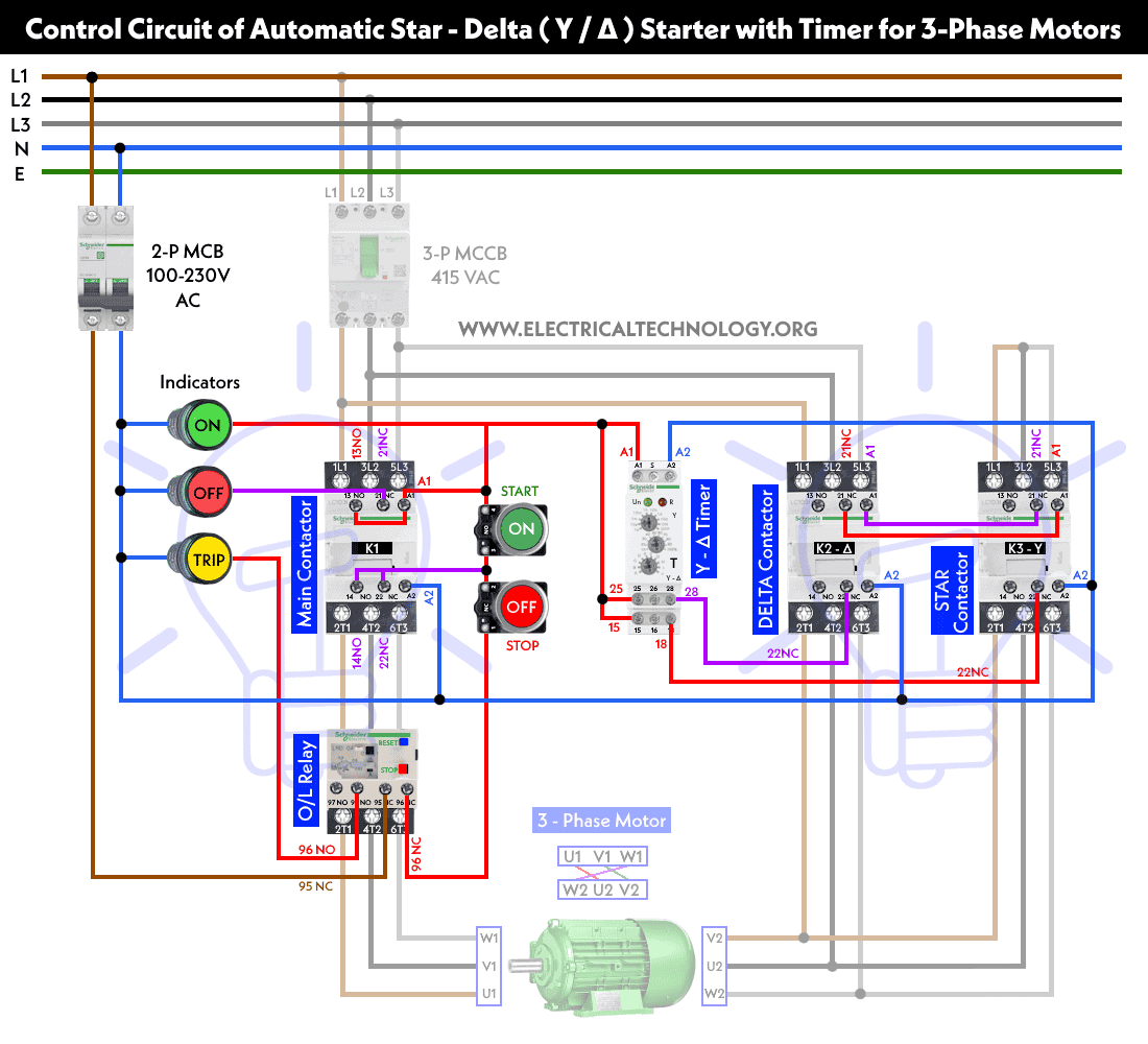
Star Delta Starter Y D Starter Power Control And Wiring

Replacement Relay Kit P N 259521 Application Manualzz
Https Encrypted Tbn0 Gstatic Com Images Q Tbn 3aand9gct8opsjeacrnf0tgzffpswqtv1fvq47pb1g1jeynw9mvvo2wbdzz8xy5k9h Qiksi8 Usqp Cau
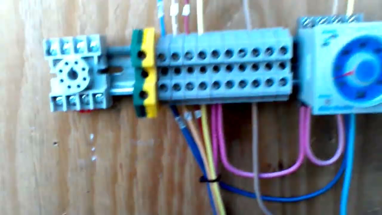
Timer switch control start and stop by relay.

Connection time delay relay wiring diagram. View is from the flat side with the catalog numbers. The older mechanical time delay relays used pneumatic dashpots or fluid filled pistoncylinder arrangements to provide the shock absorbing needed to delay the motion of the armature. Newer designs of time delay relays use electronic circuits with resistor capacitor rc networks to generate a time delay then energize a normal instantaneous electromechanical relay coil with the. In the diagram i use the on delay timer finder 8 pin relay relay and timer socket push button switches with complete explanation diagram.
8 pin relay working and connection https. A wiring diagram is a streamlined standard photographic representation of an electric circuit. Ryb electrical 572739 views. The upper two comparators operate in same manner as described in the electronic thermostat and relay circuit.
It reveals the elements of the circuit as simplified shapes as well as the power and also signal links between the gadgets. Application wiring for fixed dc time delay module figure 3. This time delay relay is made up of a simple adjustable timer circuit which controls the actual relay. It reveals the elements of the circuit as simplified shapes and also the power and signal connections in between the devices.
Kh1 series fixed time on delay external connection diagram. A low level at pin 2 is produced when the temperature is above the desired level and inhibits the square wave at pin 13 and prevents triggering of the scrs. Time delay relay wiring diagram just whats wiring diagram. Three normally open points are available so we can control three points at a time with three relay.
Assortment of time delay relay wiring diagram. 12v relay diagram used in cnc build videos. Cara kerja tdr time delay relay. The time is adjustable from 0 to about 20 seconds with the parts specified.
The current capacity of the circuit is only limited by what kind of relay you. Time delay is factory preset to one specific time 5 seconds for example. A time delay relay is a relay that stays on for a certain amount of time once activated. This is the staircase wiring with timer i shown how to use relay with timer as reset and hold switch.
Module load at pin 2 is a relay coil. This post is about the staircase timer wiring diagram. A wiring diagram is a streamlined conventional photographic depiction of an electric circuit. Control circuit diagram.
Handson 8pin Time Delay On Relay How To Wire It Youtube
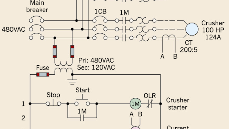
The Basics Of Current Sensing Relays Ec M

Industrial Motor Control Timing Relays
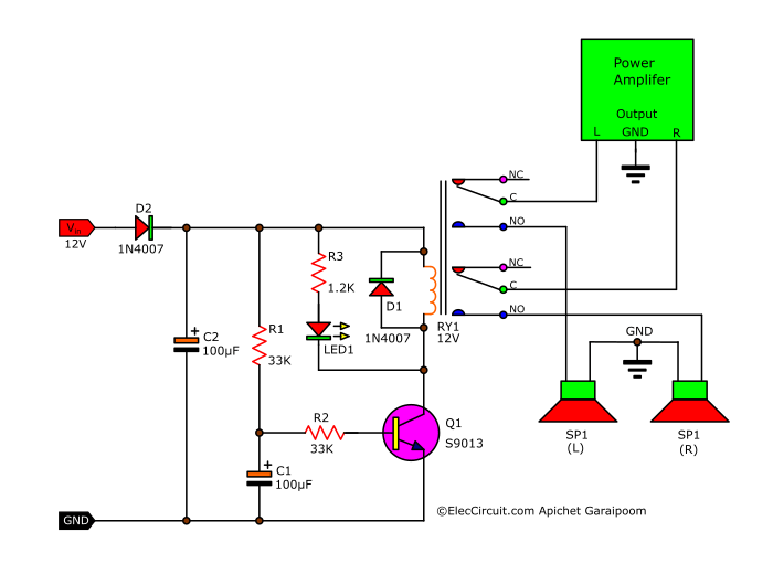
Simple Speaker Delay Circuit Eleccircuit Com

Two Simple 24 Hour Timer Circuit Schematics

The Beginner S Guide To Wiring A Star Delta Circuit Factomart
Https Encrypted Tbn0 Gstatic Com Images Q Tbn 3aand9gctl2oybnpogmtrsqb Gqto0qxljpkpzkrkdyopoikj9dukhkuadcz5dxlpwoqcmxeg Usqp Cau

Ac 220 Remote Control Everything

Staircase Timer Wiring Diagram Using On Delay Timer And Relay
