Control Schematic Symbols
6f5067 Control Wiring Diagram Symbols Wiring Resources
Devices Symbols And Circuits Electrical Circuits Electric

5 Best Images Of Motor Control Schematic Diagram Symbols House
Junction is a point where two or more things are joined.

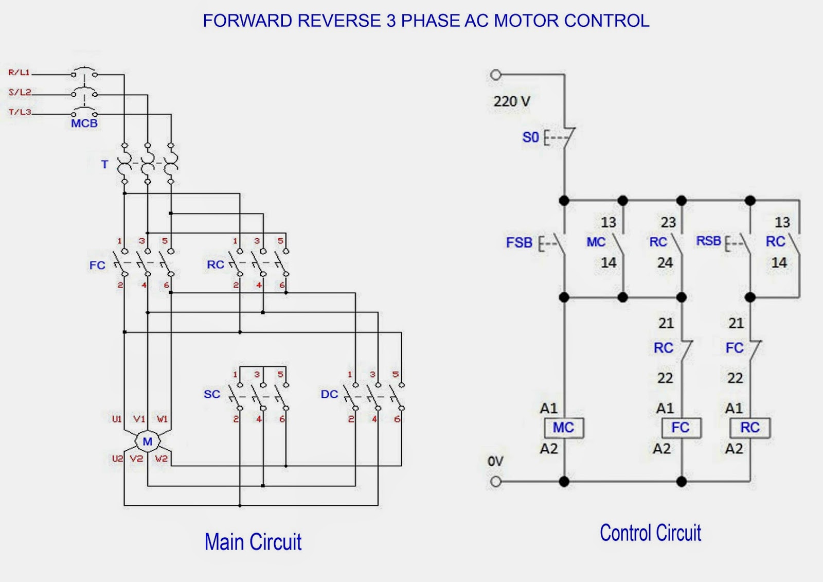
Control schematic symbols. This schematic shows both the control circuit and the motor circuit. Process tools such as valves valves instruments and pipelines are identified by code. Industrial control system diagram shapes. Wire is a metal drawn out into the form of a thin flexible thread or rod.
The symbols contained in p id represent equipment such as actuators sensors and controllers. Schematic diagrams do not always show both control and motor connections. Reference for pictures symbols. This article gives some of the frequently used symbols for drawing the circuits.
In this convention the hot and neutral power conductors are drawn as vertical lines near the edges of the page with all loads and switch contacts drawn between those lines like rungs on a ladder. Schematic symbols and circuit design help. These panels may be small as shown in figure 2 or very large as required to house the necessary. Hydraulic and pneumatic picture symbols for fluid power schematics define their function in engineering drawings diagrams or plans.
Pneumatic circuit symbols representing these valves provide detailed information about the valve they represent. Symbols show the methods of actuation the number of positions the flow paths and the number of ports. Operated valve solenoid valve 21 distance relay 23 temperature control device. Directional air control valves are the building blocks of pneumatic control.
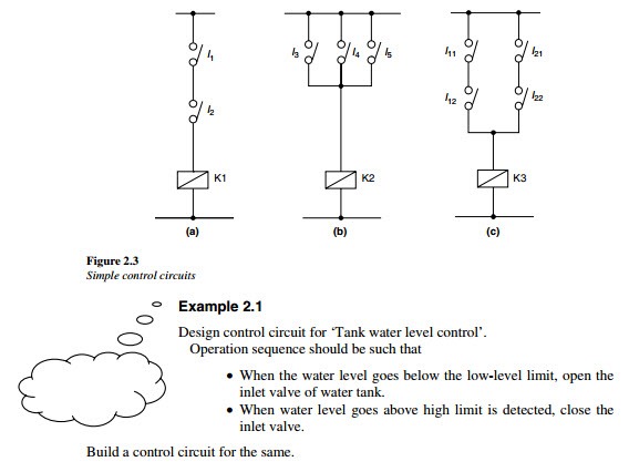
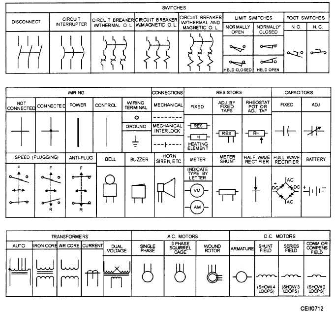
Circuit symbols the following are the circuit symbols commonly used in motor related schematic diagrams. Many schematic diagrams show only the control circuit. Panel wiring techniques electrical control panels are available in all shapes and sizes to suit the particular requirements of the situation. The first circuit to be discussed is a basic control circuit used throughout industry.
These are mostly we used for draw circuit diagrams. Industrial control system diagram symbols. There are some standard symbols to represent the components in a circuits. An alternative to the conventional schematic diagram in ac power control systems is the ladder diagram.
The codes are based on the size type of fluid being drained type of pipe connection such as using bolt or flang and the status of the valve status normally close or normally open. 8 control power disconnecting device 9 reversing device 10 unit sequence switch 11 multifunction device 12 overspeed device 13 synchronous speed device 14 underspeed device 15 speed or frequency matching device 20 elect. Figure 914 shows a start stop push button circuit. Pneumatic circuit symbols explained.

Wiring Symbols Motor Control Zubashech Com

Electrical Symbols On Wiring And Schematic Diagrams Electrical

Flow Control Valves Hydraulic Symbology 204
Control And Power Connections
Basic Wiring For Motor Control Technical Data Guide Eep
Devices Symbols And Circuits Reading And Understanding

Electrical And Electronic Drawing Industrial Controls
Schematic Pneumatic Symbols

E01ab7 3 Phase Wiring Schematic Symbols Wiring Library
