Control System Logic Diagram

Gate Control System Of Dam Using Programmable Logic Controller
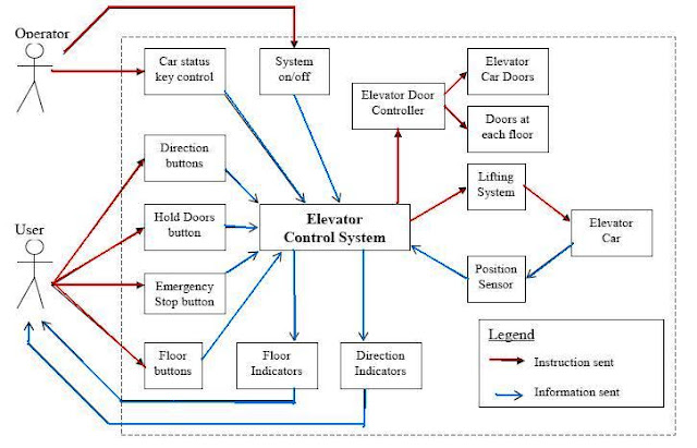
Elevator Control System Electrical Knowhow

Edge
Simple pneumatic and logic control system a relay control system for the simple system of figure lc 1 is also shown.

Control system logic diagram. But eventually we will add the point lists sequences and system diagrams so the full context of the logic can be understood. Latching rung to operate the system through master start and stop pb. This page contains links to several university control design standards that include both specifications and control drawings that include system and logic diagrams. Basically a measurement in a fuzzy logic system can be partly true that is if yes is 1 and no is 0 a fuzzy measurement can be between 0 and 1.
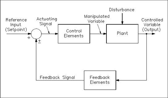
Logic diagrams have several applications in investigations and are most often developed in an iterative fashion. A block diagram is a pictorial representation of the cause and effect relationship between the input and output of a physical system. To read and interpret logic diagrams the reader must understand what each of the specialized symbols represent. The simplest form of a block diagram is the block and arrows diagram.
This schematic diagram represents a type of programming frequently referred to as ladder logic by industrial electricians. The use of logic symbology results in a diagram that allows the user to determine the operation of a given component or system as the various input signals change. Control system is a device or system that gives commands to manage the behavior of other devices or systems. Elevator logic description rung 0000.
For now the examples are just the control logic for a particular process. A control system is a device or set of devices to manage command direct or regulate the behavior of other devices or systems. A block diagram provides a means to easily identify the functional relationships among the various components of a control system. The two parts of a relay are both shown in this diagram.
Fuzzy logic is an attempt to apply the easy design of logic controllers to the control of complex continuously varying systems. A cascaded control system where the output of one controller acts as the setpoint for another controller to follow appears in sama diagram form like this. I also plan to add examples of control logic diagrams that are developed with the logic diagram tool we share on the logic diagram tool page as time permits. Electrical relays figure lc 2.
I should also mention that you can get a copy of the system diagram associated with the logic on the system diagram page of the web site. As shown in the event tree logic diagram in figure 314 in the early stages of an investigation they can be used to illustrate credibly possible reasons conditions and events to assist in determining the cause scenarioas shown in figure 315 they can point the investigators to.

Adjustable Speed Drive Programmable Logic Controllers Control

Ks 9439 Logic Control Diagram Free Diagram

Guide To Industrial Motor Control System Maxim Integrated

Plc Ladder Logic Symbols Motor Control Circuits Ladder Logic
The Basics Of Process Control Diagrams Technology Transfer Services
Simple Plc Program For Lighting Control System

Electrical And Electronic Drawing Industrial Controls Part 2

Flight Control System Description Support
Industrial Control System Definition Trend Micro Sg
